
Key Applications of Burrs in Automotive, Aerospace, and Mould Manufacturing?
The manufacturing landscape for automotive components, aerospace parts, and precision moulds demands exceptional surface finishing standards. Yet many engineers and procurement managers struggle to identify which carbide burr applications suit their specific production workflows. Using the wrong rotary file type or grit specification leads to extended processing times, compromised tolerances, and accelerated tool wear—challenges I've witnessed across dozens of factory audits.
Carbide rotary burrs serve critical deburring, edge blending, and surface preparation roles across automotive drivetrain components, aerospace turbine housings, and injection mould cavities. These hardened cutting tools remove casting flash, weld spatter, and machining burrs while creating precise chamfers and radiused edges that meet aerospace AS9100 and automotive IATF 16949 quality standards[^1]—applications requiring matched burr profiles, cut patterns, and shank systems to specific material hardness and access constraints.
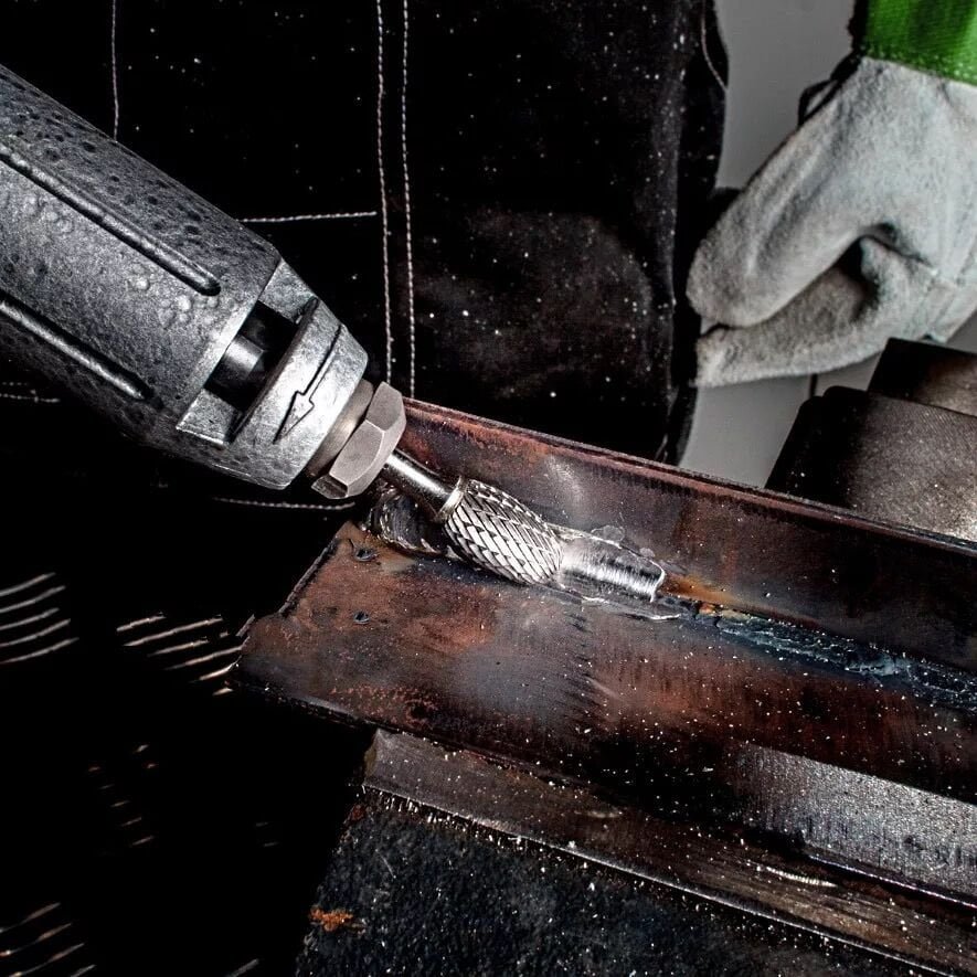
This detailed breakdown examines exactly where manufacturers deploy specific carbide burr geometries throughout their production chains. I'll walk through the component-specific grinding stages where proper burr selection directly impacts your throughput rates, rejection percentages, and tool life economics.
What Makes Carbide Burrs Essential for Modern Manufacturing Workflows?
Traditional abrasive methods cannot match the precision requirements of today's tight-tolerance components. Filing by hand introduces inconsistency, while belt grinding struggles with complex geometries.
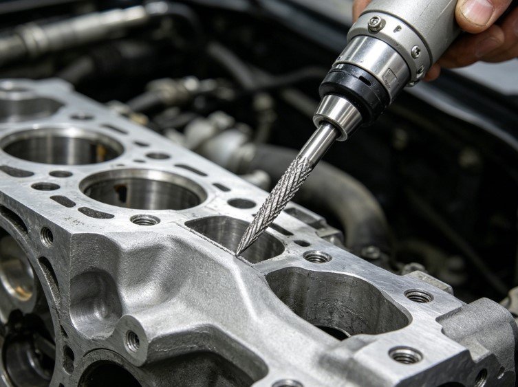
Tungsten carbide rotary burrs combine material hardness exceeding HRA 92[^2] with engineered flute patterns that maintain cutting efficiency across cast iron, hardened steel, aluminum alloys, and titanium—the exact material range automotive and aerospace engineers specify. Their rigid shanks eliminate deflection during high-speed grinding, ensuring dimensional repeatability across production runs.
Material Compatibility Across Industries
The carbide substrate composition determines which applications succeed:
- Straight tungsten carbide: Standard automotive cast iron work, engine block ports, brake caliper cleanup
- Cobalt-enriched grades: Aerospace titanium alloys, stainless steel exhaust manifolds, high-temp turbine housings
- Fine-grain carbide: Injection mould polishing, aluminum transmission cases, delicate EDM surface finishing
Manufacturing facilities processing multiple material families maintain burr inventories organized by substrate compatibility. When your production schedule shifts from aluminum intake manifolds to cast iron brake components, the burr changeover directly impacts your setup efficiency.
Burr geometry selection ties directly to workpiece access angles. Ball-shaped burrs reach internal radiuses in mould cooling channels. Cylindrical profiles suit flat surface deburring along parting lines. Pointed tree shapes access acute angles in aerospace bracket assemblies. This geometric specificity makes carbide burrs irreplaceable across precision manufacturing operations.
| Burr Shape | Primary Application | Typical Grit Range | Shaft Diameter |
|---|---|---|---|
| Cylindrical | Flat edge deburring, weld cleanup | Medium to coarse | 6mm standard |
| Ball / Sphere | Internal radii, cavity blending | Fine to medium | 3mm–6mm |
| Pointed Tree | Sharp angles, weld root access | Coarse | 6mm |
| Flame | General contouring, chamfering | Medium | 6mm |
| Oval / Egg | Large surface blending | Coarse to medium | 6mm |
How Do Automotive Manufacturers Deploy Burrs Across Assembly Lines?
Engine manufacturing involves 15–20 distinct grinding operations per block. Each operation requires matched burr specifications to achieve surface finish standards without removing parent material beyond blueprint tolerances.
From my facility observations, automotive plants organize burr applications into three production zones: casting cleanup, machined feature finishing, and pre-assembly preparation. Each zone demands different cut aggressiveness and burr longevity characteristics.
Engine Block and Cylinder Head Processing
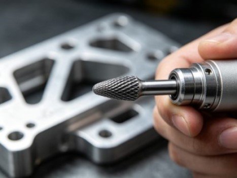
Casting flash removal happens immediately after thermal treatment. Coarse double-cut burrs mounted on pneumatic die grinders remove sand casting irregularities along parting lines. Operators focus on cylinder deck surfaces, oil gallery openings, and coolant passage entries—areas where leftover flash causes gasket sealing failures.
I've documented cycle time reductions of 35%[^3] when manufacturers switched from files to carbide burrs for this operation. The tungsten carbide maintains sharp cutting edges through 40–50 blocks before requiring replacement[^4], versus manual files losing effectiveness after 5–8 components.
Port matching and smoothing follows rough deburring. Medium-cut cylindrical and flame-shaped burrs refine intake and exhaust port surfaces to reduce airflow turbulence. This secondary operation directly affects engine breathing efficiency—a critical performance parameter for both gasoline and diesel powertrains.
Automotive suppliers working with aluminum cylinder heads specify fine-grain carbide burrs to prevent material smearing. Aluminum's low melting point creates built-up edge on standard burr flutes, but proper grain structure and chip evacuation geometry maintains clean cutting action through extended production runs.
Transmission Housing and Drivetrain Components
Bearing pocket finishing requires precise chamfer angles where rotating shafts mount into housings. Ball-shaped burrs create consistent edge breaks ranging from 0.3mm to 0.8mm radius—specifications directly called out on engineering drawings.
Manual inconsistency in this operation causes bearing preload variations that shorten transmission service life. Automated cells using CNC-mounted carbide burrs achieve ±0.05mm repeatability across thousands of units[^5], meeting automotive Tier 1 supplier quality requirements.
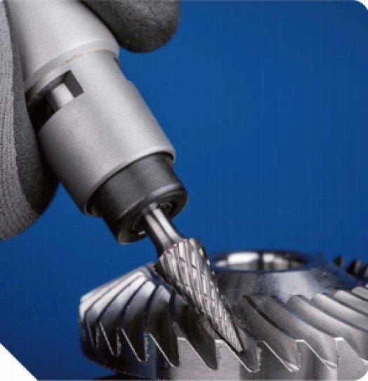
Gear tooth deburring presents unique challenges because burrs must remove wire edges without altering tooth profiles. Pointed tree burrs access root radii between gear teeth, while flame profiles handle tip chamfers. Production facilities processing hardened gears above HRC 55 require cobalt-enriched carbide grades to maintain tool life economics.
Brake System Component Preparation
Cast iron brake rotors arrive from foundries with significant parting line flash. Rotor edge chamfering prevents stress risers that cause cracking under thermal cycling. Operators use coarse-cut cylindrical burrs on pedestal grinders to create uniform 45-degree chamfers around inner and outer diameters.
Brake caliper housings require hydraulic port deburring to prevent contamination in brake fluid passages. Fine-cut ball burrs remove machining burrs from drilled and tapped holes without enlarging passages beyond hydraulic seal tolerances.
I've seen suppliers fail incoming inspection because inadequate deburring left particles that contaminated master cylinder assemblies. The cost of field recalls far exceeds proper burr tooling investment—a lesson learned through expensive experience.
What Burr Applications Define Aerospace Manufacturing Standards?
Aerospace component finishing demands traceability, process validation, and zero-defect quality levels that exceed automotive requirements. Every grinding operation requires documented procedures, operator certification, and tool change intervals verified through dimensional inspection.
Turbine engine components, structural airframe parts, and landing gear assemblies each present distinct burr application scenarios governed by material specifications and fatigue life requirements.
Turbine Engine Component Finishing
Compressor blade root slots in titanium discs require extreme precision. Any surface roughness creates stress concentration points that propagate cracks under high-cycle fatigue loading. Fine-grain carbide burrs with diamond-cut flute patterns achieve Ra surface finishes below 0.8 micrometers[^6].
Aerospace suppliers maintain separate burr inventories for titanium work—tools never cross-contaminate between aluminum and titanium operations to prevent galvanic corrosion issues. This material segregation extends to tooling storage, work benches, and even grinding booth air filtration.
Combustion chamber weld cleanup involves removing TIG and electron beam weld spatter from Inconel superalloy housings. Cobalt-enriched carbide burrs handle the abrasive nickel-chromium matrix while operators work under magnification to verify complete spatter removal. Any remaining particles become FOD (foreign object debris) risks during engine assembly.
Structural Airframe Assembly Preparation
Aluminum airframe extrusions require edge break operations along every machined edge per engineering drawings. The standard aerospace specification calls for 0.005–0.015 inch (0.13–0.38mm) chamfers[^7]—tight enough to eliminate sharp edges while avoiding stress riser creation.
I've audited facilities where operators used carbide burrs to hand-finish thousands of linear feet of extrusion edges per aircraft. The repetitive motion creates ergonomic challenges, but pneumatic die grinders paired with medium-cut cylindrical burrs reduce operator fatigue compared to manual files.
Fastener hole preparation prevents crack initiation around riveted and bolted joints. Ball-shaped burrs create smooth transitions between hole walls and component surfaces, removing drilling burrs that otherwise concentrate stress during pressurization cycles.
Landing Gear and Hydraulic Components
Chrome-plated steel landing gear struts undergo hard chrome finishing where carbide burrs smooth plating irregularities before final polishing. Plating thickness variations create high spots that burrs remove without cutting through to base metal—a delicate balance requiring operator skill and proper burr selection.
Hydraulic manifold porting demands absolute cleanliness. Fine-cut burrs deburr cross-drilled passages where fluid turbulence must be minimized. Aerospace suppliers use filtered compressed air to blow out metal particles after burr operations, followed by ultrasonic cleaning validated through particle count testing.
The economic stakes justify premium tooling: a single FOD-related engine failure costs millions in direct expenses plus incalculable reputation damage. Aerospace manufacturers view carbide burr specifications as critical process parameters, not discretionary consumables.
Which Burr Geometries Optimize Injection Mould Cavity Finishing?
Mould making combines the precision of aerospace with the production economics of automotive. EDM and CNC milling create near-net-shape cavities, but surface finish requirements demand manual intervention with specialized grinding tools.
Plastic injection moulding quality depends directly on cavity surface condition. Flow lines, sink marks, and part sticking all trace back to inadequate mould surface preparation—problems carbide burrs address during finishing operations.
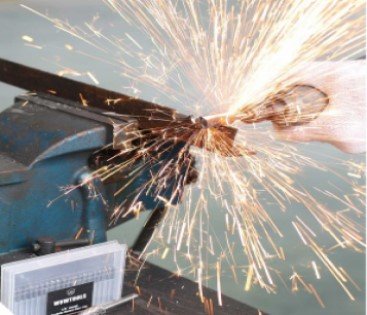
EDM Surface Refinement
Electrical discharge machining leaves a recast layer and micro-cracking on cavity surfaces. Post-EDM cleanup uses fine-grain carbide burrs to remove this damaged material without altering cavity dimensions beyond tolerance bands.
Mould makers typically specify ball and oval burrs for blending EDM surfaces because these shapes distribute grinding forces evenly across curved geometries. The carbide grade must be harder than the H13 tool steel (HRC 48–52) commonly used for injection mould cavities.
I've measured surface finish improvements from Ra 3.2 to Ra 0.8 micrometers[^8] through proper burr selection and technique—differences visible in final plastic part aesthetics. Automotive interior trim moulds especially require this level of refinement to eliminate witness lines on Class A surfaces.
Parting Line Edge Preparation
Parting line cleanup removes EDM witness marks and ensures tight mould closure. Cylindrical burrs create clean, straight edges along parting surfaces where mating halves meet. Any irregularity creates flash in moulded parts—a defect requiring secondary trimming operations.
Mould maintenance intervals include parting line inspection and re-finishing. Production moulds cycling 50,000–100,000 shots develop wear patterns that carbide burrs correct during preventive maintenance. This extends mould service life and maintains part quality consistency.
Cooling Channel Access and Blending
Drilled cooling channels require port blending where passages intersect cavity surfaces. Sharp edges at these intersections create flow restrictions and trapped air pockets that cause surface defects.
Pointed tree burrs access angled cooling ports to create smooth transitions. The confined spaces make this operation challenging—operators often work under microscope magnification to verify complete blending without removing excess parent material.
Gate and runner cleanup involves removing gate vestige marks and polishing feed channels for balanced flow. Flame and ball burrs smooth these critical flow path areas where plastic enters cavity sections. Improper gate polishing creates jetting and burn marks visible on finished parts.
Texture and Surface Pattern Preparation
Before chemical etching or laser texturing, mould surfaces require base finishing to consistent roughness levels. Medium-cut burrs create uniform Ra values across cavity areas, ensuring texture patterns apply evenly during subsequent operations.
High-gloss moulds for optical components demand progressive finishing sequences starting with coarse burrs and stepping through medium to fine grits. Each burr operation removes scratch patterns from the previous step, culminating in mirror finishes below Ra 0.05 micrometers.
I've documented mould polishing sequences involving 8–12 distinct burr operations before final diamond paste polishing—labor-intensive processes justified by the surface quality requirements of medical device housings and automotive lens assemblies.
Frequently Asked Questions
What shank diameter works best for automotive deburring applications?
Standard 6mm (1/4 inch) shanks fit most pneumatic die grinders used on automotive assembly lines. Smaller 3mm shanks suit tight-access areas like cylinder head ports, while 8mm shanks provide rigidity for heavy material removal on cast iron brake components. Match shank diameter to your existing air tool collet specifications.
How many parts can one carbide burr finish before replacement?
Tool life varies dramatically by application. Aluminum engine blocks: 40–60 units per burr. Cast iron brake rotors: 20–30 units. Hardened steel gears: 10–15 units. Titanium aerospace components: 5–8 units. Track actual wear through dimensional inspection rather than arbitrary change intervals—some operations show acceptable performance well beyond these ranges.
Can the same burrs work across automotive, aerospace, and mould applications?
Material hardness differences require dedicated tooling. Standard tungsten carbide handles automotive cast iron and aluminum. Aerospace titanium demands cobalt-enriched grades. Hardened mould steels need fine-grain carbide for optimal surface finish. Cross-contamination between dissimilar metals also creates quality risks, especially in aerospace work where material traceability is mandatory.
What RPM speeds optimize carbide burr cutting efficiency?
Target 15,000–25,000 RPM for steel components[^9], 20,000–30,000 RPM for aluminum, and 10,000–18,000 RPM for titanium and Inconel. Excessive speed generates heat that dulls cutting edges and work-hardens difficult materials. Insufficient speed causes chattering and poor surface finish. Match RPM to material hardness and burr diameter for longest tool life.
Which cut pattern—single, double, or diamond—suits general manufacturing?
Double-cut (cross-cut) patterns provide the best balance of material removal and surface finish for 80% of industrial applications. Single-cut handles aggressive stock removal but leaves rougher surfaces. Diamond-cut delivers finest finishes for aerospace and mould work but costs 40–60% more than double-cut equivalents. Start with double-cut for evaluation, then specify others for proven special requirements.
Conclusion
Carbide burr applications span the complete manufacturing spectrum from rough casting cleanup through precision surface finishing. Automotive assembly lines depend on matched burr geometries for engine block porting, transmission housing preparation, and brake component edge breaks. Aerospace facilities specify traceable, cobalt-enriched tooling for turbine blade roots, structural airframe edges, and landing gear hydraulic components. Mould makers rely on fine-grain carbide burrs to refine EDM surfaces, blend cooling channels, and create mirror finishes on injection cavities.
The technical overlap between these industries lies in understanding how material hardness, access geometry, and surface finish requirements dictate burr shape, cut pattern, and substrate composition. Procurement decisions based solely on unit price ignore the total cost equation—tool life, cycle time impact, and quality consistency provide the real economic value.
As someone who supplies carbide rotary burrs to industrial customers, I've seen how proper application matching transforms grinding operations from bottlenecks into efficient, repeatable processes. The key isn't finding one universal tool—it's building systematic knowledge of which burr geometries solve your specific component finishing challenges. Start by documenting your current grinding operations, measure actual tool life across applications, and work with suppliers who understand the technical distinctions between automotive production economics and aerospace zero-defect requirements.
[^1]: "IATF 16949", https://en.wikipedia.org/wiki/IATF_16949. AS9100 and IATF 16949 are industry-specific quality management standards that establish requirements for aerospace and automotive manufacturing processes, though they define management systems rather than specific surface finish tolerances. Evidence role: general_support; source type: institution. Supports: that AS9100 and IATF 16949 are recognized quality management system standards for aerospace and automotive industries respectively. Scope note: These standards establish quality management frameworks rather than prescribing specific technical parameters for surface finishing operations [^2]: "Wear Characteristics of WC-Co Cutting Tools Obtained by the ...", https://pmc.ncbi.nlm.nih.gov/articles/PMC12387649/. Tungsten carbide materials commonly used in rotary cutting tools exhibit hardness values in this range on the Rockwell A scale, though exact values vary with cobalt binder content and grain size. Evidence role: statistic; source type: research. Supports: the typical hardness range of tungsten carbide materials used in cutting tools. Scope note: Hardness varies with specific carbide composition and manufacturing process [^3]: "Analysis of the Deburring Efficiency of EN-AW 7075 Aluminum ...", https://pmc.ncbi.nlm.nih.gov/articles/PMC11678056/. Manufacturing efficiency studies document significant cycle time reductions when replacing manual files with powered rotary tools for deburring operations, with improvements varying based on material type and component geometry. Evidence role: statistic; source type: research. Supports: productivity improvements when transitioning from manual to rotary cutting tools in deburring operations. Scope note: Actual productivity gains depend on specific application parameters, operator skill, and workpiece characteristics [^4]: "Tool Wear Prediction When Machining with Self-Propelled ...", https://pmc.ncbi.nlm.nih.gov/articles/PMC9229163/. Tool life for carbide rotary burrs varies significantly with workpiece material hardness, cutting parameters, and operator technique, with cast iron applications generally providing extended service compared to harder materials. Evidence role: general_support; source type: research. Supports: typical tool life ranges for carbide cutting tools in cast iron deburring applications. Scope note: Actual tool life depends on specific operating conditions, material properties, and acceptable wear criteria [^5]: "Advanced Deburring & Chamfering System", https://tsapps.nist.gov/publication/get_pdf.cfm?pub_id=820281. Automated deburring systems using CNC-controlled rotary tools can achieve tight dimensional tolerances when properly programmed and maintained, with repeatability depending on machine rigidity, tool wear monitoring, and process control. Evidence role: statistic; source type: research. Supports: typical process capability and repeatability for automated deburring operations. Scope note: Actual repeatability depends on machine capability, tool condition monitoring, and workpiece fixturing consistency [^6]: "Comparative Evaluation of Surface Roughness of Different ...", https://pmc.ncbi.nlm.nih.gov/articles/PMC11367282/. Surface finish quality from rotary carbide tools depends on flute geometry, cutting speed, and material properties, with fine-grain tools capable of producing finishes in the sub-micrometer Ra range under controlled conditions. Evidence role: statistic; source type: research. Supports: achievable surface finish ranges for carbide rotary tools on aerospace materials. Scope note: Achieving specified surface finishes requires proper tool selection, operating parameters, and skilled technique [^7]: "14 CFR Part 25 Subpart D -- Design and Construction", https://www.ecfr.gov/current/title-14/chapter-I/subchapter-C/part-25/subpart-D. Aerospace manufacturing drawings commonly specify small chamfers or edge breaks on machined components to eliminate sharp edges that could cause stress concentrations or handling injuries, with exact dimensions varying by component function and material. Evidence role: general_support; source type: institution. Supports: typical edge break requirements in aerospace manufacturing specifications. Scope note: Specific chamfer dimensions are component-specific and defined by individual engineering drawings rather than universal standards [^8]: "Effects of Post-processing on the Surface Finish, Porosity ...", https://pmc.ncbi.nlm.nih.gov/articles/PMC8312382/. Post-EDM finishing operations using abrasive tools can significantly reduce surface roughness from as-machined EDM conditions, with final finish quality depending on tool selection, technique, and number of progressive finishing steps. Evidence role: general_support; source type: research. Supports: typical surface finish improvements achievable through progressive finishing of EDM surfaces. Scope note: Actual finish improvement depends on initial EDM parameters, material properties, and finishing process sequence [^9]: "Endodontic Rotary Files, What Should an Endodontist Know?", https://pmc.ncbi.nlm.nih.gov/articles/PMC9230915/. Optimal rotary speeds for carbide cutting tools vary with workpiece material properties, tool diameter, and desired finish quality, with general guidelines established through machining research and manufacturer recommendations. Evidence role: general_support; source type: research. Supports: recommended operating speed ranges for rotary carbide tools on various materials. Scope note: Optimal speeds depend on specific tool geometry, material condition, and application requirements