
Tool Selection Tips for Optimized Deburring Processes
Deburring is one of those finishing steps that looks simple on paper but causes real headaches on the shop floor. When your deburring process is slow, inconsistent, or leaving scratches on finished workpieces, the problem often traces back to one root cause: the wrong tool for the job. The right selection strategy changes everything.
Choosing the correct deburring tool comes down to matching four key variables: burr type, workpiece material, access geometry, and desired surface finish. Carbide rotary burrs are the most versatile option for industrial deburring, but optimizing your process means selecting the right cut style, tooth geometry, and shank diameter for each specific application. A systematic selection approach reduces cycle time, protects workpiece surfaces, and extends tool life.
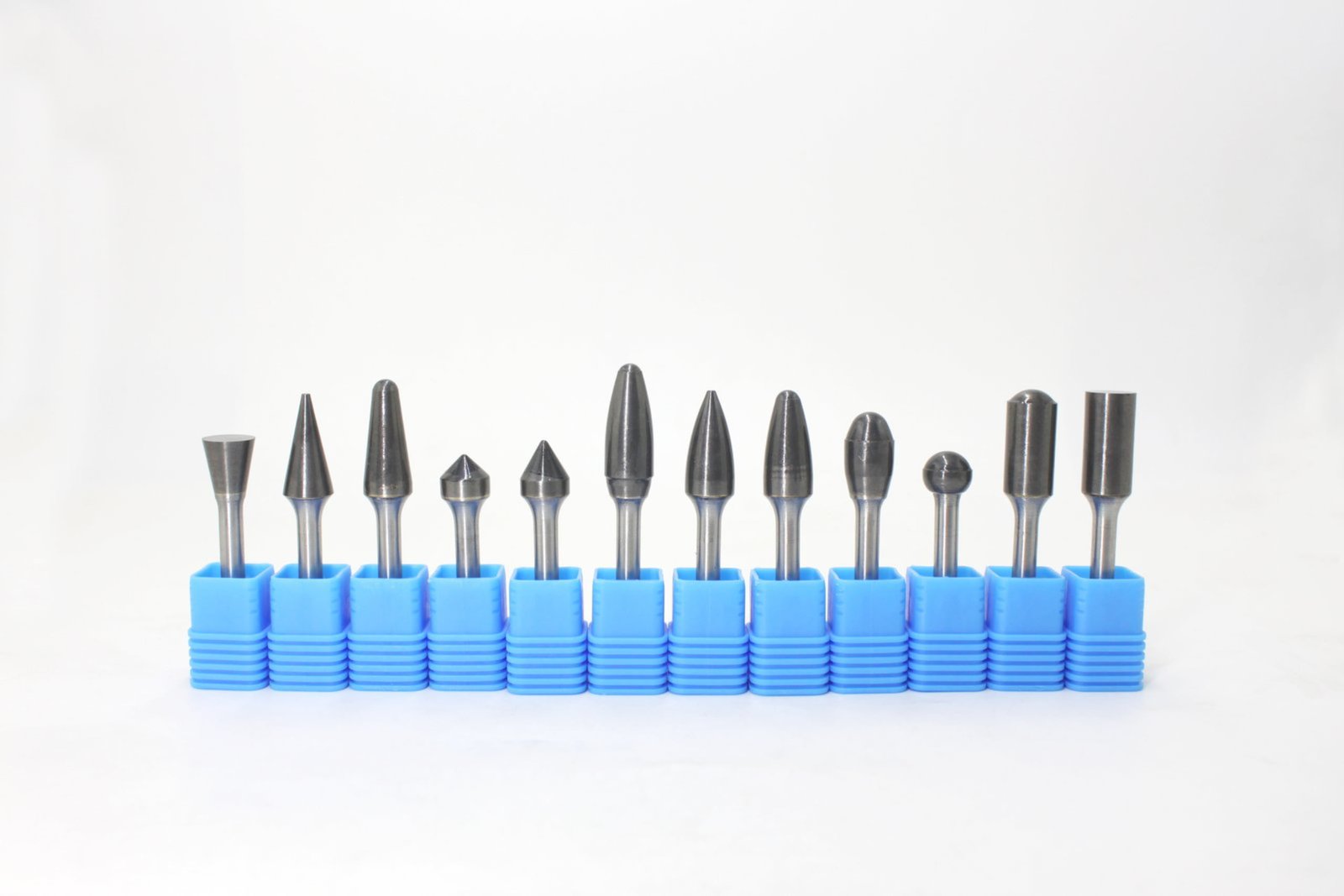
The four variables above are easy to list and surprisingly easy to get wrong. Most inefficiencies I see in deburring operations come from one of three habits: using a single all-purpose burr for every job, prioritizing price over geometry fit, or skipping the cut style decision entirely. The sections below break down each selection factor with the detail it actually deserves.
Why Does Burr Type Matter So Much for Tool Selection?
Many operators treat all burrs as roughly the same obstacle. They are not. A thin, feathery rollover burr on aluminum behaves completely differently from a thick, hardened breakout burr on stainless steel[^1] — and treating them the same way guarantees either a damaged workpiece or a worn-out tool.
The type of burr — rollover, breakout, Poisson, or tear burr — determines the cutting forces required and the geometry that will remove material cleanly. Mismatching tool geometry to burr type leads to chattering, workpiece gouging, and premature tool wear. Identifying your burr type before selecting a tool is the single most effective step in optimizing a deburring process.
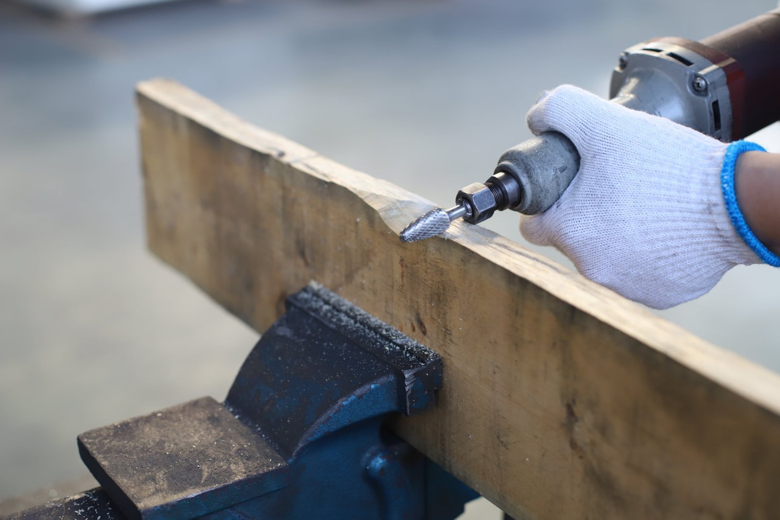
Understanding burr formation mechanics gives you a real advantage when specifying tooling. Let me walk through the most common types and what they demand from a cutting tool.
The Four Main Burr Types
- Rollover burr: The most common type, formed when material folds over an edge rather than breaking away cleanly. Thin and flexible. Common in milling and turning operations on softer materials.
- Breakout burr: Forms at the exit point of a drill or end mill pass. Usually larger and more rigid than rollover burrs. Requires more aggressive material removal.
- Poisson burr: A lateral displacement burr caused by compressive stress. Relatively low profile but tightly bonded to the workpiece surface.
- Tear burr: An irregular, jagged burr from shearing operations. Unpredictable shape makes consistent tool contact difficult.
Matching Tool Geometry to Burr Type
| Burr Type | Recommended Burr Shape | Cut Style | Notes |
|---|---|---|---|
| Rollover | Cylinder, Flame | Single cut | Light engagement needed |
| Breakout | Ball nose, Tree | Double cut | More aggressive stock removal |
| Poisson | Taper, Inverted cone | Single cut fine | Surface contact must be controlled |
| Tear burr | Ball nose, Oval | Double cut | Irregular geometry needs flexibility |
The shape of the carbide rotary burr matters as much as the cut style. A ball-nose burr lets you follow irregular contours without digging into the base material. A cylindrical burr gives you flat, consistent contact on straight edges. Selecting the wrong shape — even with the right cut style — introduces uneven pressure that can scratch or gouge finished surfaces.
> Practical rule: If your workpiece surface is showing scratches after deburring, the first question is not "am I pressing too hard?" — it is "am I using the right tooth geometry for this burr type?"
How Does Workpiece Material Influence Deburring Tool Selection?
Hardness and ductility vary enormously across the materials industrial buyers process. A tool optimized for aluminum will perform poorly — and potentially dangerously — on hardened steel or titanium. I have seen operators damage both tools and parts simply by ignoring this variable.
Workpiece material directly determines the required carbide grade, cut style, and chip clearance geometry of the deburring tool. Soft, ductile materials like aluminum need single-cut or aluminum-specific chip-breaker geometries to prevent clogging. Hard materials like stainless steel and titanium require fine double-cut or diamond-cut burrs with higher carbide hardness grades.
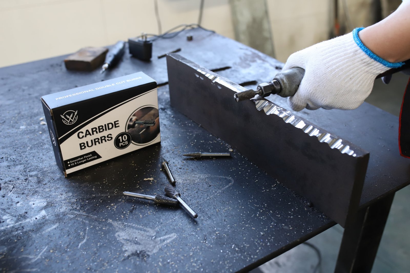
Getting the material match right protects your workpiece finish and dramatically extends tool service life. Here is a practical breakdown.
Soft and Non-Ferrous Materials (Aluminum, Copper, Plastics)
These materials present a specific problem: loading. Soft chips pack into flute spaces and create a rubbing, non-cutting contact that scratches the surface and overheats the tool[^2].
Key selection criteria:
- Use single-cut (standard cut) or aluminum-cut burrs with wide flute spacing
- Choose burrs with a positive rake angle to pull chips away cleanly
- Larger flute pitch reduces clogging on ductile materials
- Coarser tooth spacing is better than finer for aluminum
Medium-Hardness Steels (Carbon Steel, Cast Iron)
This is the broadest category in most industrial shops. The balance here is between cutting speed and finish quality.
- Double-cut burrs work well — the cross-hatch pattern produces smaller chips and smoother finishes
- Medium carbide grades (typically YG6 or equivalent) balance toughness and wear resistance
- Avoid overly coarse geometries that leave visible tool marks
Hard and Exotic Materials (Stainless Steel, Titanium, Hardened Steel)
These materials require the most careful selection. Aggressive cuts can work-harden the surface of stainless steel, making subsequent passes even harder[^3].
- Fine double-cut or diamond-cut burrs minimize heat generation
- Higher cobalt carbide grades (e.g., YG8) offer better toughness against vibration[^4]
- Lower RPM with higher torque produces better results than high-speed shallow cuts
- Shorter tool reach reduces deflection and chatter
Quick Reference: Material vs. Recommended Cut Style
| Material | Cut Style | Carbide Grade Note |
|---|---|---|
| Aluminum, plastics | Single cut / Aluminum cut | Standard grade sufficient |
| Carbon steel | Double cut | Medium grade |
| Stainless steel | Fine double cut | Higher cobalt content preferred |
| Titanium | Fine double cut | Specialized grade recommended |
| Cast iron | Single cut | Standard to medium grade |
| Hardened steel | Diamond cut | Verify with supplier |
Which Tool Geometry Should You Choose for Complex Workpiece Shapes?
Deburring a flat edge on a simple part is straightforward. The real selection challenge appears when buyers need to reach internal cavities, cross-drilled holes, undercuts, or tight radii. Poor geometry selection here causes inefficiency — or simply makes the operation impossible without scratching surrounding surfaces.
For complex workpiece geometries, burr shape selection is the primary decision. Ball-nose and oval burrs access curved internal surfaces. Tree-shaped and tapered burrs reach into drilled holes and blind cavities. Flame-shaped burrs are effective on contoured edges. Matching the burr profile to the access geometry eliminates the need for multiple tool changes and reduces cycle time.
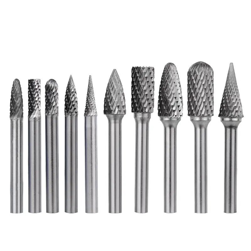
Beyond shape, two additional geometry variables deserve attention: shank diameter and flute length. Both affect reach and rigidity.
Burr Shape Selection by Application
| Burr Shape | Best Application | Caution |
|---|---|---|
| Cylinder (plain end) | Flat surfaces, side deburring | Can gouge corners if angled |
| Cylinder (radius end) | Blending edges and fillets | Good general-purpose shape |
| Ball nose | Concave surfaces, internal radii | Limited contact area on flat surfaces |
| Tree (radius end) | Drilled holes, countersinks | Verify diameter fits hole |
| Taper (radius end) | Angled slots, V-grooves | Control feed direction carefully |
| Flame | Contoured edges, curved profiles | Follow workpiece contour consistently |
| Oval / Egg | Porting, blending cavities | Versatile for mixed contours |
| Inverted cone | Back-deburring, undercuts | Requires sufficient clearance |
Shank Diameter and Reach Considerations
A longer flute length provides more reach, but it also reduces rigidity. Every millimeter of unsupported length introduces potential for deflection and chatter[^5].
Practical guidelines:
- Use the shortest flute length that accesses the feature — never default to maximum length
- Match shank diameter to your spindle's collet capacity — 6mm and 8mm shanks are the most common industrial standards
- For deep cavities, use extended shank burrs rated for the application rather than improvising with standard tools at extended projection
- Check that the burr's maximum diameter clears the entry opening with at least 0.5mm radial clearance on each side
RPM and Feed Rate Interaction
Geometry selection is inseparable from operating parameters. A correctly shaped burr run at the wrong speed produces the same poor results as a wrong shape run correctly.
- Surface feet per minute (SFM) should drive RPM selection, not arbitrary settings[^6]
- Harder materials need lower SFM; softer materials tolerate higher SFM
- Consistent feed pressure matters more than feed speed — irregular pressure causes chatter marks
How Do You Evaluate a Carbide Rotary Burr Supplier's Quality?
For procurement teams and distributors, tool performance is directly tied to carbide quality, manufacturing consistency, and coating options. A low-cost burr that wears out in two operations is more expensive than a higher-cost burr that runs reliably for twenty[^7].
When evaluating carbide rotary burr suppliers, the key quality indicators are carbide grade consistency, runout tolerance (typically under 0.02mm for precision applications), flute geometry uniformity, and surface finish of the cutting edges. Request material certifications, inspection reports, and production samples before committing to volume orders. Verify claims with independent testing where application demands are critical.
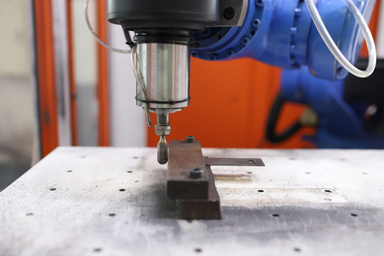
Quality evaluation has several practical dimensions that procurement teams should work through systematically.
Key Quality Indicators to Request From Suppliers
- Carbide grade specification (e.g., YG6, YG8, or equivalent ISO grade) — ask for mill certificates
- Runout tolerance at the shank — critical for surface finish and tool life
- Flute geometry consistency across a production batch — visual and dimensional inspection
- Brazing quality (for brazed-shank designs) — inspect the joint under magnification
- Surface treatment — uncoated, TiAlN, or diamond coating options for specific materials
Questions to Ask Before a Volume Order
- What carbide grade and binder content is used for each product line?
- What is the dimensional tolerance on shank diameter and overall length?
- Can you provide an inspection report from a recent production batch?
- What is the recommended operating RPM range for each tool?
- Do you offer application-specific recommendations or technical support?
Working with a supplier who can answer these questions clearly — and provide documentation — reduces procurement risk significantly compared to sourcing on price alone.
Frequently Asked Questions
What is the most common reason deburring leaves scratches on the workpiece?
Scratching almost always results from one of three causes: using a burr with too coarse a cut for the material, operating at excessive speed for the burr geometry, or using the wrong burr shape that forces flat cutting surfaces against a curved workpiece profile. Review cut style and shape before adjusting pressure or speed.
When should I use a single-cut burr versus a double-cut burr?
Use single-cut burrs for soft, ductile materials like aluminum, copper, and plastics where chip clearance is the priority. Use double-cut burrs for steel and harder materials where a finer finish and smaller chip size improve control and surface quality. Double-cut burrs also tend to run more smoothly on harder materials.
How do I know if my carbide rotary burr is worn out?
Key signs include increased vibration or chatter during cutting, visible dulling or chipping of cutting edges, a noticeable increase in cutting force needed to maintain feed rate, and a degraded surface finish on the workpiece. Worn burrs should be replaced promptly — continuing to use them accelerates workpiece damage.
Can one carbide burr handle multiple materials?
A double-cut carbide burr in a medium grade can handle a range of steel alloys adequately. However, for aluminum, you should use a geometry specifically designed for non-ferrous materials. Using the wrong cut style across material types increases tool wear and risks workpiece damage. Dedicated tooling by material type is the better practice for production environments.
What RPM should I use for carbide rotary burrs?
RPM depends on burr diameter and workpiece material. Smaller diameter burrs require higher RPM to achieve the correct surface cutting speed. As a general starting point, a 6mm carbide rotary burr on steel typically runs between 20,000 and 25,000 RPM, while the same burr on aluminum may run higher. Always follow the supplier's recommended operating range and verify for your specific application.
Conclusion
Optimizing a deburring process starts with systematic tool selection — not trial and error. Matching the carbide rotary burr geometry to your specific burr type, workpiece material, and part geometry eliminates the most common sources of inefficiency: slow cycle times, workpiece scratching, and premature tool wear. Supplier quality is equally important; the best selection decision on paper produces poor results if the tool itself is inconsistently manufactured. When evaluating tooling for your operation, treat cut style, burr shape, carbide grade, and supplier documentation as equally important decision variables. If you need guidance selecting the right carbide rotary burr for your specific deburring application, reach out — we are glad to support your evaluation process.
[^1]: "Burr (edge)", https://en.wikipedia.org/wiki/Burr_(edge). Research on burr formation mechanisms confirms that rollover burrs form through plastic deformation when material folds over an edge, while breakout burrs result from fracture at tool exit points, producing structurally distinct features with different removal requirements. Evidence role: mechanism; source type: research. Supports: the mechanical formation and structural differences between rollover and breakout burrs in metal machining. Scope note: The source may describe burr formation generally rather than specifically comparing aluminum versus stainless steel behavior [^2]: "Built-up edge", https://en.wikipedia.org/wiki/Built-up_edge. Studies of chip formation in aluminum machining demonstrate that ductile materials produce continuous chips that can adhere to tool flutes, creating built-up edge conditions that increase friction, generate heat, and degrade surface finish. Evidence role: mechanism; source type: research. Supports: the mechanism by which chip accumulation in cutting tools creates rubbing contact and thermal issues when machining ductile materials. [^3]: "Modulating Surface Machining to Optimize Work ...", https://ui.adsabs.harvard.edu/abs/2023JMEP...3210363W/abstract. Metallurgical research on austenitic stainless steels confirms significant strain hardening during machining, with surface hardness increases of 200-300% reported in aggressive cutting conditions, creating progressively more difficult cutting conditions in subsequent tool passes. Evidence role: mechanism; source type: research. Supports: the work-hardening behavior of stainless steel under mechanical deformation during cutting operations. [^4]: "Study of the Apparent Fracture Toughness of a Thermally ...", https://upcommons.upc.edu/bitstreams/e1f17c81-9917-4b7d-8011-8011b8c82f5f/download. Materials science research on cemented carbides shows that increased cobalt content enhances fracture toughness and impact resistance by providing a more ductile binder phase, though at the cost of reduced hardness and wear resistance. Evidence role: mechanism; source type: research. Supports: the effect of cobalt binder content on the toughness and fracture resistance of tungsten carbide. [^5]: "Machining vibrations", https://en.wikipedia.org/wiki/Machining_vibrations. Machining dynamics research demonstrates that tool deflection increases with the cube of unsupported length, while natural frequency decreases, making extended tools progressively more susceptible to chatter vibrations and dimensional errors. Evidence role: mechanism; source type: research. Supports: the relationship between tool overhang length and deflection/vibration in machining operations. [^6]: "Surface feet per minute", https://en.wikipedia.org/wiki/Surface_feet_per_minute. Machining engineering principles establish that cutting speed (surface feet per minute) represents the actual velocity at the cutting edge and should determine spindle RPM through the relationship RPM = (SFM × 3.82) / diameter, ensuring consistent cutting conditions across different tool sizes. Evidence role: general_support; source type: education. Supports: the standard engineering practice of calculating RPM from surface cutting speed (SFM) based on tool diameter. [^7]: "Total cost of ownership", https://en.wikipedia.org/wiki/Total_cost_of_ownership. Manufacturing cost analysis demonstrates that total tooling cost per workpiece depends on tool life, with cost-per-part calculations showing that tools with 10x longer life justify significantly higher purchase prices when tool change time and consistency are factored into production economics. Evidence role: general_support; source type: research. Supports: the economic principle that tool cost per part depends on tool life rather than purchase price alone. Scope note: The specific cost advantage depends on labor rates, production volume, and tool change time; the principle is general rather than providing specific cost ratios