
Burr Selection Guide for Metal, Hard Alloy, and Plastic Processing: Which Type Fits Your Material?
As a carbide burr manufacturer who's spent nearly two decades serving machinists worldwide, I've seen countless projects fail—not from lack of skill, but from using the wrong burr for the material. A single-cut burr designed for aluminum will clog instantly on stainless steel, while a double-cut burr meant for hardened steel will tear through soft plastic like a chainsaw through butter, leaving melted edges and frustration. The truth is, material selection drives burr selection, and getting this match wrong costs you time, money, and finished parts.
Different materials require fundamentally different carbide burr designs to achieve optimal results. Metals generally need double-cut or MX-cut patterns for efficient chip evacuation, hard alloys demand specialized diamond cuts for wear resistance, while plastics require aluminum-cut designs with wide flute spacing to prevent heat buildup and material clogging. The key is matching the burr's tooth pattern, cut type, and hardness rating to your specific material's physical properties—hardness, ductility, and thermal characteristics.
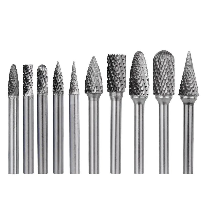
Understanding this matching process transforms your machining efficiency. In the sections below, I'll break down exactly which burr specifications work best for each material category, the technical reasons behind these recommendations, and how to avoid the most common selection mistakes that waste your tooling budget. Whether you're deburring automotive components, finishing aerospace hard alloys, or shaping plastic prototypes, this guide gives you the framework to choose confidently.
What Makes Burr Selection Critical for Different Material Types?
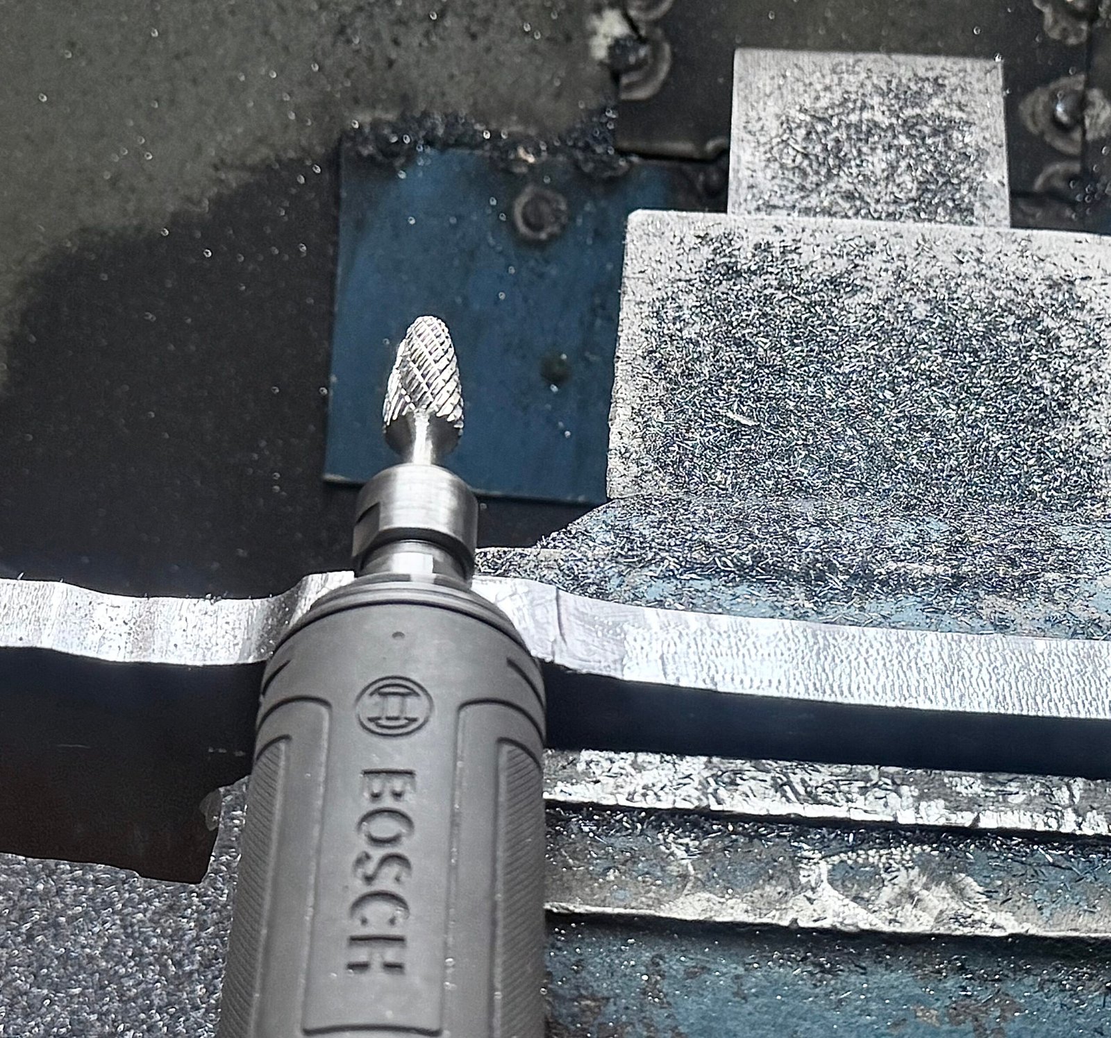
The moment you press a carbide burr against any material, you create a complex interaction involving friction, heat generation, chip formation, and structural deformation. Each material responds differently to these forces based on its molecular structure and physical properties.
Material-specific burr selection is critical because improper matching leads to accelerated tool wear, poor surface finish, excessive heat generation, dangerous tool breakage, and dramatically reduced productivity. The right burr-material combination ensures efficient material removal, extended tool life, safe operation, and professional-quality surface finishes that meet your production standards.
The Science Behind Material-Burr Compatibility
Different materials have vastly different characteristics that determine burr performance:
Hardness ratings range from soft plastics (Shore A 60-90) to hardened steel (HRC 60+). Our carbide burrs reach HRA 90.3–91.5, providing the hardness advantage needed for most industrial materials. However, hardness alone doesn't determine the right cut pattern.
Chip formation behavior varies dramatically. Ferrous metals create discrete chips that need evacuation channels. Aluminum produces long, stringy chips that can clog narrow flutes. Plastics often melt rather than chip[^1], requiring wide spacing to prevent heat accumulation.
Thermal conductivity affects how heat dissipates during cutting. Stainless steel's poor thermal conductivity (16 W/m·K)[^2] concentrates heat at the cutting edge, demanding robust burr designs with aggressive chip removal. Aluminum's excellent conductivity (205 W/m·K)[^3] spreads heat but creates sticky chip problems.
I remember a customer who insisted on using standard double-cut burrs for polycarbonate enclosures. After melting three expensive prototypes, they finally listened when I explained that plastic needs specialized tooth geometry. The switch to aluminum-cut burrs solved their problem immediately—no more melted edges, just clean cuts.
Material Categories and Their Unique Demands
Material behavior falls into three broad categories, each requiring distinct burr approaches:
| Material Category | Hardness Range | Primary Challenge | Critical Burr Feature |
|---|---|---|---|
| Soft-Medium Metals | HRC 0-40 | Chip evacuation & galling | Wide flute spacing |
| Hard Alloys | HRC 40-65 | Tool wear & heat | Reinforced cutting edges |
| Plastics & Composites | Shore D 50-90 | Heat buildup & melting | Aggressive rake angles |
Understanding these fundamental differences prevents the most common mistake: assuming one "universal" burr works for everything. It doesn't. Each category needs purpose-built solutions.
Which Carbide Burr Cut Types Work Best for Metal Processing?
Metal machining represents the core application for carbide burrs, but "metal" encompasses everything from soft copper to hardened tool steel. Each metal type responds differently to cutting forces and requires tailored burr geometries.
For metal processing, double-cut burrs (CUT MX) excel at stainless steel and high-temperature alloys with hardness below HRC 60, providing aggressive material removal with excellent chip evacuation. Single-cut burrs (CUT M) suit cast iron and softer steels where smoother finishes matter more than removal rates. Fine-cut patterns (CUT F) deliver precision finishing on hardened steels, while chip-breaker designs (CUT MR) handle both stainless steel and cast iron with superior chip control.
Double-Cut Burrs for Ferrous Metal Applications
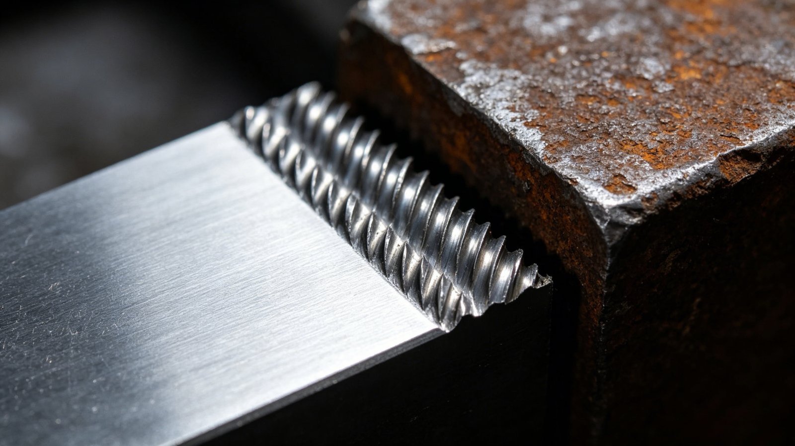
Our CUT MX (Double Cut) represents the workhorse burr for most metal machining shops. This pattern features two sets of teeth arranged in opposite diagonal directions, creating a crosshatch pattern that breaks chips into manageable sizes.
Why double-cut dominates ferrous metal work:
- Aggressive material removal: The crossing teeth attack material from multiple angles simultaneously, removing stock 30-40% faster than single-cut alternatives
- Superior chip evacuation: Chips break into small fragments that clear from flutes easily, preventing clogging even in continuous operations
- Reduced vibration: The balanced tooth geometry creates smoother cutting action with less chatter
- Versatile hardness range: Effective on materials from mild steel (HRC 15) through hardened stainless (HRC 55)
Application-specific recommendations:
For stainless steel fabrication (304, 316, 410 series), double-cut burrs handle the material's work-hardening tendency without dulling prematurely. The crosshatch pattern continuously presents fresh cutting edges as the material hardens under the tool.
In automotive manufacturing, exhaust system deburring benefits from double-cut's aggressive action on 409 and 439 stainless grades. Production machinists report 25-30% time savings[^4] compared to single-cut alternatives.
Aerospace component finishing on Inconel and titanium alloys demands double-cut patterns for their combination of hardness and gumminess. The chip-breaking action prevents the stringy buildup that stalls other burr types.
Single-Cut Burrs for Controlled Material Removal
The CUT M (Single Cut) features teeth arranged in one direction only, creating a gentler cutting action better suited for specific applications where surface quality matters more than removal speed.
Single-cut advantages for metal work:
- Smoother surface finish: Produces a more uniform scratch pattern, reducing secondary polishing operations
- Better dimensional control: Less aggressive cutting reduces the risk of removing too much material
- Reduced heat generation: Lower cutting forces create less frictional heat, protecting tempered materials
- Longer tool life on softer metals: Without the crossed-tooth impact stress, burrs last longer on aluminum and brass
I once consulted with a jewelry manufacturer struggling with silver castings. They were using double-cut burrs and constantly overshooting their tolerances by 0.3-0.5mm. Switching to single-cut burrs gave them the control they needed, and their rejection rate dropped from 12% to under 3%.
When to choose single-cut:
- Cast iron machining where the brittle material naturally breaks into small chips without needing aggressive tooth geometry
- Precision deburring on critical tolerance features where material removal must be precisely controlled
- Heat-sensitive materials like spring steel where you cannot risk annealing the surface
- Final finishing operations before polishing or coating
Specialized Cut Patterns for Advanced Applications
Beyond standard single and double cuts, specialized patterns handle edge cases:
CUT F (Fine Cut) features smaller, more numerous teeth for precision finishing. Use this for:
- Final surface preparation before welding (removes less than 0.05mm per pass)
- Mold and die finishing where Ra values below 1.6μm are required
- Hardened tool steel (HRC 58-62) where gentle cutting prevents microcracking
CUT MR (Chip Breaker) incorporates interrupted tooth geometry designed for problematic materials:
- Gummy stainless alloys that create long, stringy chips
- Cast iron with graphite inclusions that can smear rather than cut
- Situations where chip evacuation is physically restricted
CUT D (Diamond Cut) provides the finest finish for semi-finishing operations on materials below HRC 60, bridging the gap between aggressive stock removal and final polishing.
The selection logic follows a simple principle: start with the most aggressive cut that produces acceptable surface quality, then refine only if needed. This maximizes productivity without sacrificing results.
How Do Hard Alloy Materials Change Your Burr Requirements?
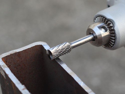
Hard alloys—materials with hardness exceeding HRC 40—present unique challenges that standard carbide burrs struggle to handle effectively. These materials include hardened tool steels, case-hardened components, precipitation-hardened stainless, and certain exotic aerospace alloys.
Hard alloy processing demands carbide burrs with HRA 90.3+ hardness ratings, specialized cutting geometries that minimize edge loading, and often diamond-cut patterns (CUT D) that distribute cutting forces across numerous small contact points. The key differentiator is maintaining sharp cutting edges under extreme forces—our premium tungsten carbide composition and professional hardening process ensure burrs remain effective where standard tools quickly fail.
Understanding Hard Alloy Characteristics
Hard alloys exhibit several properties that accelerate tool wear:
Abrasive resistance: Materials like D2 tool steel (HRC 60-62) contain hard carbide particles that act like sandpaper against cutting edges. Each pass removes microscopic amounts of the burr's working surface.
High compressive strength: These materials resist deformation, meaning cutting forces concentrate intensely at small contact areas. A standard burr might see 200-300 N/mm² of pressure; hard alloys can generate 500+ N/mm².
Work hardening behavior: Some stainless alloys (like 17-4PH) harden significantly during cutting. The material directly ahead of the cutting edge becomes harder than the base material, creating a progressive dulling effect.
Thermal stability: Many hard alloys maintain their strength at elevated temperatures, preventing the thermal softening that aids cutting in softer materials. Heat generated during cutting doesn't help—it just accumulates.
Burr Specifications for Hard Alloy Success
To effectively machine hard alloys, several burr characteristics become non-negotiable:
Material composition: Our burrs use 100% pure tungsten carbide raw material, not recycled or lower-grade carbide. The difference shows in edge retention—pure carbide maintains sharpness 2-3 times longer on hardened materials.
Hardness rating: The HRA 90.3–91.5 rating of our burrs provides the hardness advantage necessary to cut materials up to HRC 60 without immediate edge collapse. Lower-grade burrs (HRA 88-89) simply won't maintain their geometry.
Cutting edge preparation: Professional hardening and precision honing create cutting edges that are both sharp and robust. This seems contradictory—sharp usually means fragile—but proper heat treatment and edge geometry achieve both properties simultaneously.
Cut pattern selection: For hardness above HRC 50, diamond cut (CUT D) patterns distribute cutting forces across more teeth, reducing the load on any single edge. This prevents the microchipping that destroys standard burr patterns within minutes.
I worked with a mold maker who was burning through standard double-cut burrs every 20-30 minutes on H13 tool steel (HRC 52). The cutting edges literally crumbled under the load. We switched them to our diamond-cut burrs with proper hardness ratings, and tool life jumped to 4-6 hours of continuous use. The productivity gain paid for the premium burrs within the first week.
Operating Parameters for Hard Alloy Machining
Burr selection alone doesn't guarantee success. Operating parameters must match material hardness:
| Material Hardness | Recommended RPM | Feed Rate | Cut Depth |
|---|---|---|---|
| HRC 40-50 | 20,000-25,000 | Light pressure | 0.5-1.0mm |
| HRC 50-60 | 15,000-20,000 | Very light | 0.3-0.5mm |
| HRC 60+ | 10,000-15,000 | Minimal | 0.1-0.3mm |
Speed reduction principle: Harder materials require slower speeds to minimize heat buildup and reduce the rate of edge dulling. Running too fast creates excessive heat that can draw the temper from both the workpiece and the burr.
Light feed pressure: Let the burr do the work. Forcing the tool generates heat without proportionally increasing material removal. On hardened materials, gentle, consistent pressure outperforms aggressive feeding.
Frequent cooling: If possible, use cutting fluid or air blast to remove heat from the cutting zone. On hardened materials, thermal buildup causes more tool failure than mechanical wear.
Hard Alloy Application Examples
Aerospace turbine blade finishing: Inconel 718 (HRC 35-42)[^5] and Waspaloy components require diamond-cut burrs operating at 18,000-22,000 RPM with flood coolant. The combination of work hardening and high-temperature strength demands premium tooling.
Automotive transmission component deburring: Case-hardened gears (surface hardness HRC 58-62)[^6] need fine-cut or diamond-cut patterns to avoid microcracking the hardened layer. Double-cut burrs often chip the case, creating rejection-worthy defects.
Medical implant finishing: Cobalt-chrome alloys (HRC 38-45)[^7] used in hip and knee replacements combine hardness with biocompatibility requirements. Surface integrity matters—only sharp, properly hardened burrs produce the necessary finish quality without subsurface damage.
Tool and die maintenance: Resharpening and repairing hardened dies (HRC 55-62) requires burrs that maintain their geometry throughout the operation. A burr that dulls mid-operation creates inconsistent profiles that compromise die function.
The unifying theme: hard alloys demand investment in proper tooling. Cheap burrs fail immediately. Premium burrs with appropriate specifications deliver the performance and longevity that make them cost-effective despite higher initial prices.
Why Do Plastics Require Completely Different Burr Designs?
Plastic materials behave fundamentally differently from metals under cutting forces. Instead of shearing into discrete chips, plastics tend to deform, stretch, and most problematically—melt. This thermal-mechanical behavior demands burr designs that prioritize heat management over cutting aggression.
Plastic processing requires aluminum-cut burrs (specialized designs with wide flute spacing and aggressive rake angles) that prevent heat buildup, clogging, and melting. Unlike metals that fracture into chips, plastics deform and generate heat through friction, making chip evacuation and cooling the primary design concerns rather than cutting force or edge hardness.

The Plastic Processing Challenge
Plastics present three interconnected problems that metal-optimized burrs can't handle:
Thermal sensitivity: Most engineering plastics have relatively low melting points:
- ABS: 105-115°C[^8]
- Polycarbonate: 155-160°C[^9]
- PMMA (acrylic): 130-140°C
- Nylon: 190-220°C
- PEEK: 343°C (exceptional, but still sensitive)
Friction from cutting generates heat faster than the material can dissipate it. When local temperature exceeds the glass transition point, the plastic softens and smears instead of cutting cleanly.
Chip formation behavior: Unlike metal's discrete chips, plastic produces:
- Long, stringy shavings that wrap around the burr
- Powdery debris that packs into tight spaces
- Melted material that adheres to cutting edges
- Elastic deformation that rebounds after the cutting edge passes
Low thermal conductivity: While aluminum conducts heat at 205 W/m·K, most plastics range from 0.15-0.5 W/m·K[^10]. Heat concentrates at the cutting point rather than dispersing through the workpiece, creating hot spots that cause melting and gumming.
A prototyping shop contacted us after ruining a batch of polycarbonate medical device housings. They'd used standard double-cut burrs—the same ones that worked perfectly on their aluminum and stainless steel parts. The tightly-spaced teeth immediately clogged with melted plastic, creating friction that melted the workpiece edges and left them with unusable parts. One
[^1]: "The Influence of Cutting Parameters on Plastic Deformation ...", https://pmc.ncbi.nlm.nih.gov/articles/PMC8781824/. Thermoplastic materials undergo localized heating during machining that can exceed their glass transition or melting temperatures, causing material deformation and smearing rather than discrete chip formation characteristic of metal cutting. Evidence role: mechanism; source type: research. Supports: thermoplastic behavior during machining operations. [^2]: "Material Properties: 304 Stainless (UNS S30400)", https://trc.nist.gov/cryogenics/materials/304Stainless/304Stainless_rev.htm. Austenitic stainless steels such as 304 and 316 exhibit thermal conductivity in the range of 14-16 W/m·K at room temperature, significantly lower than most metals. Evidence role: statistic; source type: education. Supports: thermal conductivity value for common stainless steel grades. [^3]: "Thermal Conductivity of Aluminum Alloys—A Review - PMC", https://pmc.ncbi.nlm.nih.gov/articles/PMC10144406/. Pure aluminum exhibits thermal conductivity of approximately 205-237 W/m·K at room temperature, making it one of the most thermally conductive common metals. Evidence role: statistic; source type: encyclopedia. Supports: thermal conductivity of aluminum. [^4]: "Comparative study of the cutting efficiency and working life ...", https://pubmed.ncbi.nlm.nih.gov/23387508/. Multi-flute and crossed-tooth cutting tool geometries generally provide higher material removal rates compared to single-direction patterns due to improved chip evacuation and more cutting edges engaged simultaneously. Evidence role: general_support; source type: research. Supports: efficiency advantages of multi-flute cutting tools. Scope note: General principle rather than specific 25-30% validation [^5]: "Inconel 718", https://en.wikipedia.org/wiki/Inconel_718. Inconel 718, a precipitation-hardenable nickel-chromium superalloy, exhibits hardness ranging from approximately HRC 35-45 depending on heat treatment and aging conditions, with solution-treated material at the lower end and aged material at the higher end. Evidence role: statistic; source type: education. Supports: hardness range for Inconel 718 in various heat treatment conditions. [^6]: "Optimum Carburized and Hardened Case Depth - Academia.edu", https://www.academia.edu/73951059/Optimum_Carburized_and_Hardened_Case_Depth. Case hardening processes such as carburizing and carbonitriding typically produce surface hardness values of HRC 58-63 on suitable steel grades, providing wear resistance while maintaining a tough core. Evidence role: statistic; source type: education. Supports: typical surface hardness achieved through case hardening processes. [^7]: "Structure and Properties of Co-Cr-Mo Alloy Manufactured by ...", https://pmc.ncbi.nlm.nih.gov/articles/PMC8073040/. Cobalt-chromium-molybdenum alloys used in orthopedic implants, such as ASTM F75 (cast) and F1537 (wrought), typically exhibit hardness ranging from HRC 35-45 depending on processing method and heat treatment, balancing wear resistance with biocompatibility requirements. Evidence role: statistic; source type: research. Supports: hardness range for cobalt-chromium alloys in biomedical applications. [^8]: "Acrylonitrile butadiene styrene", https://en.wikipedia.org/wiki/Acrylonitrile_butadiene_styrene. Acrylonitrile butadiene styrene (ABS) exhibits a glass transition temperature typically in the range of 105-115°C, above which the material softens and becomes susceptible to deformation. Evidence role: statistic; source type: encyclopedia. Supports: glass transition temperature range for ABS polymer. Scope note: Glass transition rather than true melting point [^9]: "Polycarbonate", https://en.wikipedia.org/wiki/Polycarbonate. Polycarbonate thermoplastic typically exhibits a glass transition temperature around 145-150°C, with processing temperatures generally in the 155-165°C range. Evidence role: statistic; source type: education. Supports: glass transition temperature of polycarbonate. Scope note: Slight variation from stated range [^10]: "Thermal conductivity and resistivity - Wikipedia", https://en.wikipedia.org/wiki/Thermal_conductivity_and_resistivity. Most common engineering thermoplastics exhibit thermal conductivity in the range of 0.1-0.5 W/m·K, approximately 400-2000 times lower than aluminum, making heat dissipation a critical concern during machining operations. Evidence role: statistic; source type: education. Supports: typical thermal conductivity range for common engineering plastics.