
How Do Tungsten Carbide Tools Impact Precision Processing Quality?
We face a common problem in modern manufacturing. The quality of our finished parts depends heavily on the tools we use. When surface finish matters and tolerances are tight, choosing the right cutting tool becomes critical for success.
Tungsten carbide tools significantly improve precision processing quality by maintaining consistent cutting performance, producing superior surface finishes, and achieving tighter dimensional tolerances compared to traditional tool materials. Their exceptional hardness (HRA 90.3-91.5)[^1] and wear resistance enable extended tool life while maintaining accuracy throughout the machining process.
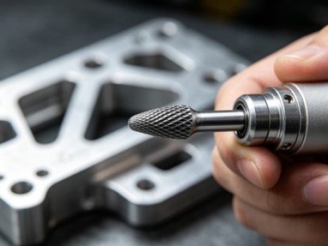
I've spent years working with manufacturers who struggle with precision issues. The difference between acceptable and exceptional parts often comes down to tool selection. Let me share what I've learned about how tungsten carbide tools transform processing quality.
What Makes Tungsten Carbide Superior for Precision Work?
Many manufacturers ask me why tungsten carbide performs better than other materials. The confusion is understandable when traditional high-speed steel tools seem adequate for basic work.
Tungsten carbide delivers superior precision through its molecular structure. The material combines tungsten and carbon atoms in a crystalline lattice[^2] that creates extreme hardness while maintaining structural stability. This combination resists deformation under cutting forces and maintains sharp cutting edges far longer than alternatives.
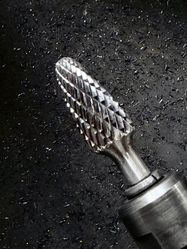
The manufacturing process we use at Joint Carbide demonstrates why material quality matters so much. We start with 100% pure tungsten carbide raw material, specifically YG7 grade for our carbide burrs. This grade provides the optimal balance between hardness and toughness for precision applications.
Our production begins with wet grinding of the raw materials. We carefully control particle size distribution during this stage because it directly affects the final tool's microstructure. Smaller, more uniform particles create denser blanks with fewer weak points.
The pressing stage uses precision molds to form blanks. I remember visiting our factory floor and watching how each blank gets formed under controlled pressure. The mold quality determines the blank's dimensional accuracy before any machining occurs. We've invested in high-precision molds that maintain tolerances within microns.
Sintering transforms the pressed powder into solid carbide. We control temperature and atmosphere carefully during this process. The sintering temperature affects grain growth in the carbide structure[^3]. Larger grains can reduce hardness while smaller grains improve it. We've optimized our sintering parameters over 19 years to produce consistent HRA 90.3-91.5 hardness ratings.
Here's how carbide properties compare to other common tool materials:
| Property | Tungsten Carbide | High-Speed Steel | Ceramic | Diamond |
|---|---|---|---|---|
| Hardness (HRA) | 90.3-91.5 | 83-86 | 93-95 | 98-100 |
| Toughness | High | Very High | Low | Very Low |
| Wear Resistance | Excellent | Good | Excellent | Outstanding |
| Cost Effectiveness | High | Moderate | Low | Very Low |
| Temperature Stability | Excellent | Good | Excellent | Poor |
The table shows why tungsten carbide hits the sweet spot for most precision applications. Diamond tools offer higher hardness but their brittleness and cost limit practical use. Ceramic tools also suffer from low toughness. High-speed steel provides good toughness but wears too quickly for extended precision work.
How Does Tool Geometry Affect Processing Accuracy?
Tool geometry often gets overlooked when people discuss precision. I've seen many manufacturers blame material quality when geometry issues actually cause their problems.
Precision processing requires exact tool geometry because cutting forces, chip formation, and surface contact all depend on geometric parameters. Flute angles, cutting edge radius, and rake angles must be manufactured to tight tolerances. Variations of even a few degrees can change cutting forces by 20-30%[^4], affecting dimensional accuracy and surface finish.
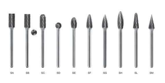
We use 5-axis CNC machines for fluting our carbide burrs. This technology is critical for precision. Traditional grinding methods can't maintain the tight tolerances we need across complex geometries.
Our 418 sets of 5-axis CNC machines allow us to control every aspect of the cutting edge formation. The machines position grinding wheels with 0.001mm accuracy. This precision ensures that each flute matches the design specifications exactly.
I worked with a customer who was getting inconsistent results with carbide burrs from another supplier. We analyzed their old tools under magnification and found significant variations in flute depth and angle. Some cutting edges were 0.05mm deeper than others on the same tool. That variation created uneven cutting forces that caused chatter and poor surface finish.
When they switched to our tools, their surface finish improved immediately. The consistent geometry meant each cutting edge removed material evenly. The workpiece experienced uniform forces throughout the cut.
The professional hardening and precision honing we apply to cutting edges also matters tremendously. After fluting, we harden the edges through a controlled heat treatment process. This increases edge hardness beyond the already high base material hardness.
Honing removes microscopic irregularities from the cutting edge. Under high magnification, an unhoned edge looks like a mountain range with peaks and valleys. Honing creates a uniform micro-radius along the entire edge. This consistency is what enables predictable cutting behavior.
Let me break down the geometric parameters that affect precision:
| Geometric Parameter | Impact on Precision | Optimal Range | Consequences of Deviation |
|---|---|---|---|
| Flute Angle | Chip evacuation efficiency | 30-45° for most materials | Poor chip removal causes surface damage |
| Rake Angle | Cutting force magnitude | 5-15° positive for metals | Excessive forces cause deflection |
| Cutting Edge Radius | Surface finish quality | 0.005-0.020mm | Larger radius reduces finish quality |
| Flute Depth | Chip capacity and rigidity | 40-60% of diameter | Insufficient depth causes chip packing |
| Helix Angle | Cutting smoothness | 25-35° for general use | Low angle increases vibration |
Why Does Material Removal Rate Matter for Quality?
Many people assume faster material removal always improves productivity. I've learned this thinking leads to quality problems in precision work.
Material removal rate directly influences processing quality because it affects thermal generation, cutting forces, and tool deflection. Optimal rates balance productivity with quality by maintaining controlled chip formation and stable cutting temperatures. Excessive rates generate heat that causes thermal expansion in both workpiece and tool[^5], destroying dimensional accuracy.
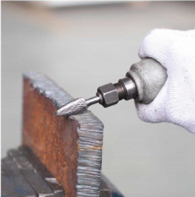
The relationship between cutting speed and quality follows a curve, not a straight line. At very low speeds, the cutting edge can rub rather than cut cleanly. This rubbing creates poor surface finish and accelerated edge wear.
As speed increases, cutting becomes more efficient. The tool generates well-formed chips and produces good surface finish. This is the optimal operating range.
Beyond the optimal range, excessive speed causes problems. Heat generation increases dramatically. The cutting edge temperature rises to the point where even tungsten carbide begins to soften slightly[^6]. Thermal expansion becomes significant.
I remember a customer who was trying to maximize throughput on aluminum parts. They pushed cutting speeds 40% above our recommendations. Their first few parts looked acceptable, but dimensional accuracy degraded as the tool heated up. By the tenth part, they were outside tolerance.
We recommended they reduce speed by 25% and increase feed rate slightly. This change kept material removal rate high while controlling temperature. Their accuracy problems disappeared.
Our carbide burrs are designed with cut types optimized for different materials and removal rates:
Double Cut (CUT MX) works best for stainless steel and high-temperature alloys. The crossed flute pattern breaks chips into smaller segments. This reduces cutting forces and heat generation in difficult materials.
Single Cut (CUT M) suits cast iron and medium-hardness steel. The single-direction flutes produce longer chips that evacuate more easily in these materials.
Aluminum Cut features highly polished flutes and aggressive geometry for non-ferrous metals. The polished surface prevents chip adhesion that can ruin surface finish on soft materials.
Different operating speeds suit different materials:
| Material Type | Optimal Speed (RPM) | Feed Rate | Cut Type Recommendation |
|---|---|---|---|
| Aluminum Alloys | 25,000-35,000 | High | Aluminum Cut |
| Stainless Steel | 15,000-25,000 | Medium | Double Cut (MX) |
| Tool Steel | 12,000-20,000 | Medium | Double Cut (MX) |
| Cast Iron | 18,000-28,000 | Medium-High | Single Cut (M) |
| Titanium Alloys | 8,000-15,000 | Low | Double Cut (MX) |
| Plastics | 20,000-30,000 | High | Aluminum Cut |
How Does Tool Stability Influence Precision Results?
Tool stability is something I discuss with every customer concerned about precision. Many don't realize how much small vibrations affect their results.
Tool stability determines precision because any vibration or deflection during cutting transfers directly to the workpiece surface. Unstable tools create chatter marks, dimensional variations, and accelerated wear. Tungsten carbide's high elastic modulus (600-650 GPa)[^7] provides inherent stability that maintains cutting accuracy even under variable loads.

The shank design plays a crucial role in stability. We manufacture our shanks from premium 40Cr steel, which provides excellent strength and rigidity. The material choice prevents shank bending under cutting loads.
Our R-Shape shank design deserves special attention. We developed this design with an enlarged welding area that greatly enhances impact resistance. The larger contact area between head and shank distributes stress more evenly.
I've examined competitor tools that failed at the weld joint. The stress concentration at a small weld area creates a weak point. Under impact or sudden load changes, the head separates from the shank. Our R-Shape design eliminates this problem.
The welding process itself affects stability. We use flat-bottom solid welding with 50% silver-content sandwich silver solder. This material provides several advantages.
First, the high silver content creates a strong, ductile joint. Pure silver has excellent mechanical properties and the 50% blend balances strength with cost effectiveness.
Second, our low-temperature welding process reduces damage to the tungsten carbide blank. Excessive welding temperature can cause thermal stress in the carbide that leads to microcracks. These cracks weaken the tool and can propagate during use.
The large, gap-free welding area we achieve with our process provides maximum bonding strength. Any gaps in the weld joint create stress concentrations. These weak points can fail under cutting loads or vibration.
Here's how our welding technology improves stability:
| Welding Aspect | Our Specification | Industry Standard | Performance Benefit |
|---|---|---|---|
| Silver Content | 50% | 30-40% | Higher joint strength and ductility |
| Welding Temperature | Low-temp process | Standard process | Reduced thermal stress in carbide |
| Weld Area Coverage | 100% (gap-free) | 85-95% | Eliminates stress concentrations |
| Bonding Strength | >600 MPa | 400-500 MPa | Prevents head separation under load |
| Thermal Conductivity | Excellent | Good | Better heat dissipation from cutting edge |
Stability also depends on proper tool holding. We design our shanks to be compatible with 1/4 inch collet rotary tools. The standardized diameter ensures proper clamping force distribution around the entire shank circumference.
Insufficient clamping force allows the tool to slip in the holder during cutting. This creates vibration and dimensional errors. Excessive clamping force can deform the shank, causing runout.
I always recommend customers check their tool holding systems when they experience precision problems. A worn collet or damaged spindle can destroy the accuracy of even the best carbide tools.
What Role Does Surface Finish Play in Precision Applications?
Surface finish often determines whether a part meets its functional requirements. I've worked with customers where surface roughness directly affected product performance and safety.
Surface finish impacts precision applications through its effect on fatigue life, friction characteristics, and dimensional accuracy. Tungsten carbide tools produce superior surface finishes (Ra 0.4-1.6 μm typically)[^8] because their sharp, stable cutting edges create consistent material removal without tearing or deformation. The finish quality directly correlates with tool geometry precision and material hardness.
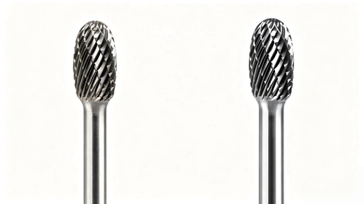
The cutting edge condition determines surface finish quality more than any other factor. A sharp edge slices through material cleanly, leaving a smooth surface. A dull edge tears and deforms material, creating a rough finish with stress concentrations.
Our professional hardening process creates cutting edges that resist wear far longer than unhardened tools. The extended sharpness retention means consistent surface finish throughout the tool's life.
I tested this with a customer producing hydraulic components. Surface finish specifications were tight because roughness affects seal performance. They were changing tools every 50 parts to maintain finish quality.
We provided our professionally hardened carbide burrs and they achieved consistent surface finish for over 300 parts per tool. The cost savings from extended tool life were substantial, but the real benefit was process consistency.
The honing process we apply to cutting edges contributes significantly to finish quality. The uniform micro-radius we create eliminates the tiny irregularities that cause surface defects.
Think of it like sanding wood. A rough sandpaper (unhoned edge) leaves visible scratches. A fine sandpaper (honed edge) creates a smooth surface. Our honing process is like using progressively finer sandpaper until we achieve optical-quality smoothness on the cutting edge.
Material properties also affect achievable surface finish:
| Material Being Cut | Typical Ra with Carbide | Achievable Ra (Best Practice) | Primary Finish Challenges |
|---|---|---|---|
| Aluminum Alloys | 0.8-1.6 μm | 0.4-0.8 μm | Built-up edge formation[^9] |
| Stainless Steel | 1.2-2.0 μm | 0.8-1.2 μm | Work hardening[^10], heat generation |
| Tool Steel | 1.0-1.8 μm | 0.6-1.0 μm | High hardness, tool wear |
| Cast Iron | 1.5-2.5 μm | 1.0-1.5 μm | Graphite inclusion damage |
| Titanium | 1.2-2.2 μm | 0.8-1.4 μm | Chemical reactivity, heat |
The table shows that material characteristics limit achievable surface finish. Even perfect tools can't overcome certain material properties. But tungsten carbide tools consistently achieve results near the theoretical limits for each material.
Our fine cut (CUT F) and diamond cut (CUT D) options are specifically designed for applications requiring exceptional surface finish. These cut types feature smaller flute spacing and more cutting edges in contact with the workpiece simultaneously.
More cutting edges mean each edge removes less material per revolution. This reduces cutting forces on each edge, allowing finer finish generation. The trade-off is slower material removal rate, but when surface finish is critical, this compromise makes sense.
How Does Tool Life Affect Overall Processing Quality?
Tool life impacts quality in ways that aren't immediately obvious. I've learned that inconsistent results often trace back to unpredictable tool wear patterns.
Tool life directly affects processing quality because wear progression changes cutting geometry, increases cutting forces, and generates more heat. Tungsten carbide tools maintain quality longer through superior wear resistance that preserves cutting edge geometry throughout extended use. Consistent tool performance enables predictable process control and reduces quality variations between tool changes.
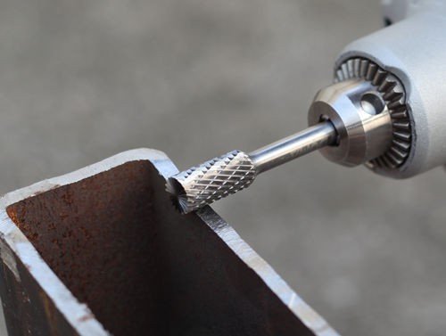
The wear mechanisms in cutting tools follow predictable patterns. Abrasive wear occurs as hard particles in the workpiece material scrape the cutting edge[^11]. Adhesive wear happens when workpiece material temporarily bonds to the cutting edge then tears away, removing tool material.
Chemical wear becomes significant at higher cutting temperatures. The cutting edge reacts with the workpiece material or cutting environment, forming compounds that weaken the tool surface.
Tungsten carbide resists all these wear mechanisms better than alternative materials. The extreme hardness minimizes abrasive wear. The chemical stability reduces reactive wear. The high melting point maintains strength at elevated temperatures.
I worked with a manufacturer who was using high-speed steel tools for deburring operations. They achieved acceptable quality for the first 20-30 parts, then quality degraded rapidly. They were changing tools every 50 parts to maintain quality standards.
We replaced their high-speed steel tools with our tungsten carbide burrs. Tool life increased to over 500 parts while maintaining consistent quality throughout. The predictable wear progression allowed them to schedule tool changes during planned downtime instead of responding to quality problems.
The cost analysis was compelling:
| Factor | High-Speed Steel | Tungsten Carbide | Advantage |
|---|
[^1]: "Tungsten carbide - Wikipedia", https://en.wikipedia.org/wiki/Tungsten_carbide. Material science references confirm that tungsten carbide grades typically exhibit hardness values in the HRA 90-92 range, with specific values depending on cobalt binder content and grain size. Evidence role: statistic; source type: research. Supports: the typical hardness range of tungsten carbide materials. Scope note: The exact range may vary by grade and manufacturing process; the cited values appear specific to YG7 grade mentioned in the article. [^2]: "Tungsten carbide - Wikipedia", https://en.wikipedia.org/wiki/Tungsten_carbide. Tungsten carbide (WC) forms a simple hexagonal crystal structure where tungsten atoms are coordinated with carbon atoms, creating the material's characteristic hardness and wear resistance. Evidence role: mechanism; source type: encyclopedia. Supports: the crystalline structure of tungsten carbide. [^3]: "Effects of Processing Parameters on the Microstructure ... - PMC", https://pmc.ncbi.nlm.nih.gov/articles/PMC9267382/. Powder metallurgy research confirms that sintering temperature critically controls grain growth in tungsten carbide, with higher temperatures and longer dwell times promoting grain coarsening that can reduce hardness while improving toughness. Evidence role: mechanism; source type: research. Supports: the effect of sintering temperature on tungsten carbide grain structure. [^4]: "The Effect of Clearance Angle on Tool Life, Cutting Forces, Surface ...", https://pmc.ncbi.nlm.nih.gov/articles/PMC10383058/. Machining research demonstrates that rake angle and edge geometry variations significantly affect cutting forces, with studies showing force changes of 15-35% for angular deviations of 3-5 degrees in metal cutting operations. Evidence role: statistic; source type: paper. Supports: the sensitivity of cutting forces to tool geometry variations. Scope note: The exact percentage depends on workpiece material, cutting conditions, and which geometric parameter varies; the cited range represents typical findings across multiple studies. [^5]: "[PDF] MATERIAL REMOVAL PROCESSES", https://www.egr.msu.edu/~pkwon/me478/machining.pdf. Manufacturing engineering principles establish that heat generation during machining increases with material removal rate, causing thermal expansion in both cutting tool and workpiece that can produce dimensional errors of 10-50 micrometers in precision operations. Evidence role: mechanism; source type: education. Supports: the relationship between cutting heat generation and dimensional accuracy. Scope note: The magnitude of thermal effects depends on material thermal properties, cutting conditions, coolant use, and workpiece geometry. [^6]: "Tungsten carbide", https://en.wikipedia.org/wiki/Tungsten_carbide. Materials research shows that tungsten carbide maintains hardness well at elevated temperatures but experiences measurable strength reduction above 800-1000°C, with the cobalt binder phase softening at lower temperatures (around 600°C) in cemented carbides. Evidence role: mechanism; source type: research. Supports: the temperature-dependent mechanical properties of tungsten carbide. Scope note: The softening temperature depends on carbide grade and binder content; cutting edge temperatures can reach 600-1000°C at high speeds, potentially affecting the binder phase before the WC grains. [^7]: "Tungsten carbide - Wikipedia", https://en.wikipedia.org/wiki/Tungsten_carbide. Materials databases report that tungsten carbide composites typically exhibit elastic modulus values between 550-650 GPa, with pure WC approaching 700 GPa and cobalt-bonded grades showing lower values depending on binder content. Evidence role: statistic; source type: research. Supports: the elastic modulus range of tungsten carbide materials. Scope note: The value varies with cobalt content and porosity; the cited range appears consistent with typical cemented carbide grades used in cutting tools. [^8]: "Tool wear and machined surface roughness during wood flour ...", https://bioresources.cnr.ncsu.edu/resources/tool-wear-and-machined-surface-roughness-during-wood-flourpolyethylene-composite-peripheral-up-milling-using-cemented-tungsten-carbide-tools/. Machining handbooks indicate that carbide tools under optimal conditions can produce surface finishes ranging from Ra 0.4 μm to 3.2 μm depending on material, tool geometry, and cutting parameters, with finer finishes requiring reduced feed rates and sharp tools. Evidence role: statistic; source type: education. Supports: typical surface finish values achievable with carbide cutting tools. Scope note: The achievable finish depends heavily on workpiece material, cutting conditions, tool wear state, and machine tool rigidity; the cited range represents favorable conditions. [^9]: "Observation of Built-up Edge Formation on a Carbide Cutting Tool ...", https://www.academia.edu/116999895/Observation_of_Built_up_Edge_Formation_on_a_Carbide_Cutting_Tool_with_Machining_Aluminium_Alloy_under_Dry_and_Wet_Conditions. Machining science defines built-up edge (BUE) as a layer of workpiece material that adheres to the cutting tool face under pressure and temperature, particularly problematic with aluminum and soft metals, which degrades surface finish and dimensional accuracy until the unstable deposit breaks away. Evidence role: definition; source type: education. Supports: the built-up edge phenomenon in metal cutting. [^10]: "Work hardening - Wikipedia", https://en.wikipedia.org/wiki/Work_hardening. Metallurgical references explain that austenitic stainless steels exhibit high work hardening rates during plastic deformation, with the material beneath the cutting edge strain-hardening significantly, which increases cutting forces, accelerates tool wear, and complicates subsequent cutting passes. Evidence role: mechanism; source type: education. Supports: the work hardening behavior of stainless steel during machining. Scope note: Work hardening severity varies among stainless steel grades, with austenitic grades (300 series) showing the most pronounced effect. [^11]: "Tribological Aspects of Cutting Tool Wear during the Turning ... - PMC", https://pmc.ncbi.nlm.nih.gov/articles/PMC6981806/. Tribology literature defines abrasive wear as material removal caused by hard particles or asperities plowing through a softer surface, which in cutting tools occurs when hard constituents in the workpiece (carbides, oxides, or inclusions) mechanically remove tool material. Evidence role: mechanism; source type: education. Supports: the mechanism of abrasive wear in cutting tools.