
The Custom Cutting Tool Manufacturing Process Explained
I remember the first time a client asked me about our manufacturing process. They wanted to know why our carbide burrs lasted longer than competitors'. That conversation opened my eyes to how little people understand about what goes into making quality cutting tools. Most buyers think all carbide burrs are the same. They are not.
Custom cutting tool manufacturing involves six critical stages: wet grinding tungsten carbide powder, precision pressing into blanks, high-temperature sintering, computer-controlled fluting, rigorous quality testing, and protective packaging for shipment. Each step directly impacts the tool's hardness, precision, and service life in your application.
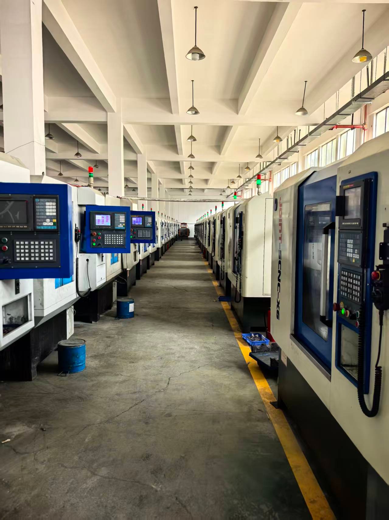
At Joint Carbide, we have refined this process over 19 years. Our three factories house 418 five-axis CNC machines. We produce 25,000 to 30,000 carbide burrs daily. But numbers mean nothing without understanding the process behind them. Let me walk you through exactly how we turn raw tungsten carbide into precision cutting tools.
What Happens During the Wet Grinding Stage?
The grinding stage determines everything that follows. Poor grinding creates weak spots that will fail under stress. I have seen competitors skip this step or rush through it. They pay for it later with customer complaints.
Wet grinding transforms tungsten carbide powder into a uniform mixture with optimal particle size distribution. Water prevents overheating during grinding, preserves material properties, and creates the consistent texture needed for pressing. This stage takes 8-12 hours depending on batch size and desired fineness.
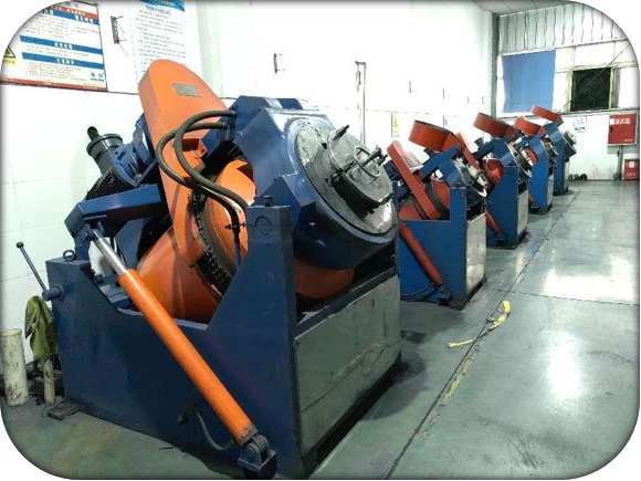
We start with 100% pure tungsten carbide powder. No fillers. No shortcuts. The grinding equipment uses ceramic-lined drums that rotate at controlled speeds. Water serves three purposes here. First, it cools the material. Tungsten carbide generates heat during grinding. Too much heat changes its molecular structure. Second, water acts as a lubricant between particles. This prevents contamination from metal-on-metal friction. Third, it creates a slurry that we can pump and filter.
The particle size matters more than most people realize. We aim for a distribution between 0.8 and 1.5 microns. Larger particles create weak bonds during sintering. Smaller particles are harder to press uniformly. Our quality control team checks particle size every two hours during grinding. We use laser diffraction analysis[^1]. If the distribution shifts outside our range, we adjust grinding time or add more material.
During grinding, we also add cobalt binder. The ratio varies based on the final tool's intended use. For standard carbide burrs, we use 6-10% cobalt[^2]. Higher cobalt content increases toughness but reduces hardness. Lower cobalt content does the opposite. This is where understanding your application matters. A tool for machining stainless steel needs different properties than one for aluminum.
The wet grinding stage also removes impurities. Even high-purity tungsten carbide contains trace elements. Our filtration system catches particles larger than 50 microns. These would become stress concentration points in the finished tool. After grinding, we drain the slurry into settling tanks. The water evaporates slowly. We control humidity and temperature during this phase. Fast drying creates cracks in the powder cake.
| Grinding Parameter | Standard Range | Impact on Quality |
|---|---|---|
| Particle Size | 0.8-1.5 microns | Affects sintering and final hardness |
| Cobalt Content | 6-10% | Balances toughness and hardness |
| Grinding Time | 8-12 hours | Ensures uniform distribution |
| Water Temperature | 15-25°C | Prevents thermal damage |
| pH Level | 7-9 | Controls chemical reactions |
How Does Pressing Transform Powder into Blanks?
Pressing looks simple. Put powder in a mold and apply pressure. But the devil lives in the details. I have seen pressing mistakes that did not show up until the tool failed in a customer's shop.
Pressing compresses wet-ground carbide powder into green blanks with 45-50% of final density. Hydraulic presses apply 100-200 MPa of pressure[^3] in controlled cycles. The blank's shape determines the final burr geometry, and pressing defects cannot be corrected in later stages.
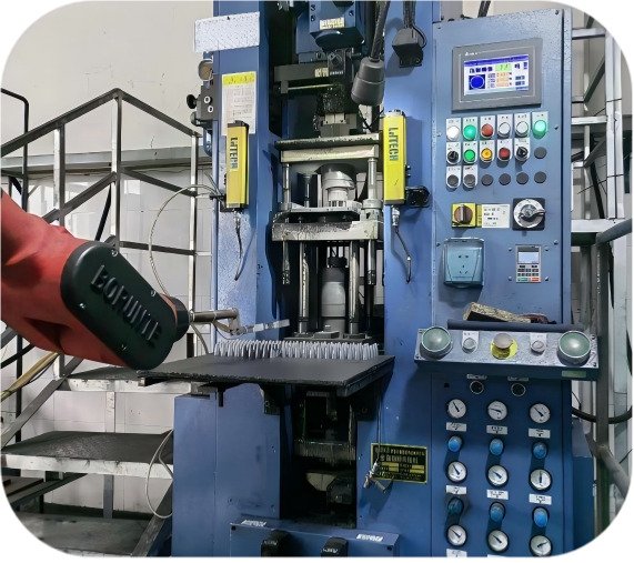
Our pressing stations use computer-controlled hydraulic systems. Manual pressing cannot achieve the consistency we need. The operator loads powder into steel dies that match our final burr shapes. We have over 200 die designs. Each one produces a specific head shape and shank configuration.
The pressing cycle has three phases. First, we apply light pressure to eliminate large air pockets. This pre-compression phase uses about 20% of final pressure. It takes 30 seconds. The powder particles rearrange without fracturing. Second, we ramp up to full pressure over 60 seconds. Fast pressure increases create cracks along grain boundaries. Slow ramping allows particles to slide past each other and settle into dense packing. Third, we hold full pressure for 90 seconds. This dwell time lets the binder flow into remaining gaps.
Pressure distribution within the die matters enormously. We design dies with tapered walls that account for friction. Powder near the die walls experiences more resistance than powder in the center. Without compensation, the blank's density varies. We use floating platens that adjust pressure based on feedback from load cells. This keeps density variation under 2% across the blank.
Temperature control during pressing prevents premature sintering. The cobalt binder can soften if friction generates too much heat. We maintain die temperature at 20-25°C using cooling channels. Some manufacturers press at higher speeds to increase throughput. They sacrifice quality for quantity. A rushed pressing cycle creates internal stresses that cause warping during sintering.
After pressing, we have green blanks. They are fragile[^4]. Handling them requires care. We place them on graphite trays in specific orientations. The blank's weight can deform it if not properly supported. Our operators receive training on handling techniques. One dropped blank wastes all the time and material invested up to that point.
Green density inspection happens here. We use ultrasonic testing to check for internal voids. X-ray inspection catches cracks that are invisible to the eye. Any blank that fails inspection goes back to grinding. We do not send problem blanks forward. Catching defects here saves money compared to finding them after sintering.
| Pressing Stage | Duration | Pressure (MPa) | Purpose |
|---|---|---|---|
| Pre-compression | 30 seconds | 20-40 | Remove large voids |
| Pressure Ramp | 60 seconds | 40-200 | Achieve target density |
| Dwell Time | 90 seconds | 200 | Stabilize blank structure |
| Release | 30 seconds | 200-0 | Prevent cracking |
What Occurs During High-Temperature Sintering?
Sintering transforms our fragile green blanks into hard cutting tools. This stage requires precision control of temperature, atmosphere, and time. Mistakes here cannot be fixed. I have toured factories where sintering furnaces looked like afterthoughts. Those companies had high scrap rates.
Sintering heats carbide blanks to 1,400-1,500°C[^5] in a controlled atmosphere, causing tungsten carbide particles to bond and shrink to final dimensions. The process takes 12-16 hours including heating, soaking, and cooling phases. Proper sintering achieves HRA 90.3-91.5 hardness[^6] and eliminates internal porosity.
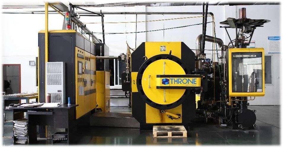
Our sintering furnaces are hydrogen atmosphere units. Hydrogen prevents oxidation at high temperatures. Even small amounts of oxygen create tungsten oxide that weakens the carbide structure. We maintain hydrogen purity above 99.9%. Flow rate is 50-100 liters per hour depending on furnace load.
The heating cycle follows a specific curve. We cannot simply set the furnace to 1,450°C and wait. Rapid heating creates thermal stress that cracks blanks. We use a five-stage heating profile. Stage one brings temperature to 600°C over four hours. This removes any remaining moisture and volatile compounds from the binder. Stage two ramps to 1,000°C over two hours. The cobalt binder melts and begins to wet the tungsten carbide particles. Stage three increases temperature to 1,450°C over three hours. This is where true sintering occurs.
During sintering, tungsten carbide particles bond through solid-state diffusion[^7]. Atoms migrate across particle boundaries. The liquid cobalt phase acts as a transport medium. Particles grow together and internal pores shrink. The blank shrinks by 15-20% in all dimensions[^8]. This shrinkage must be uniform. Non-uniform shrinkage creates dimensional errors that show up during fluting.
Stage four is the soak period. We hold 1,450°C for two hours. This allows complete homogenization of the structure. Longer soak times do not improve quality. Excessive high-temperature exposure causes grain growth. Larger grains reduce hardness and wear resistance. We monitor furnace temperature at five points. Any variation above 10°C triggers an alarm.
Stage five is controlled cooling. We reduce temperature to 600°C over four hours, then to room temperature over six more hours. Fast cooling creates residual stresses. These stresses cause spontaneous cracking days or weeks later. Some customers have reported tools that broke in the package before use. That is always a cooling problem.
Furnace atmosphere matters as much as temperature. We measure dew point, oxygen content, and hydrogen flow continuously. A leak that admits air ruins an entire furnace load. The financial loss is significant, but the schedule delay hurts worse. Our maintenance team inspects furnaces daily. We replace worn seals immediately. Prevention costs less than scrap.
After sintering, blanks are hard and ready for machining. But they have surface scale from the atmosphere interaction. We use a mild acid bath to remove this scale. The bath also reveals surface defects. Cracks show up as dark lines. Porous areas appear lighter. We inspect every blank under magnification. Pass rates above 98% indicate good process control.
| Sintering Stage | Temperature (°C) | Duration (hours) | Critical Control |
|---|---|---|---|
| Moisture Removal | 20-600 | 4 | Prevent explosive vaporization |
| Binder Melting | 600-1,000 | 2 | Uniform liquid phase formation |
| Active Sintering | 1,000-1,450 | 3 | Control grain growth |
| Homogenization Soak | 1,450 | 2 | Achieve target hardness |
| Controlled Cooling | 1,450-20 | 10 | Minimize residual stress |
How Does CNC Fluting Create the Cutting Edges?
Fluting transforms a sintered carbide blank into a functional cutting tool. This is where our 418 five-axis CNC machines earn their cost. Manual fluting cannot achieve the precision we need. I have compared hand-fluted tools to CNC-fluted ones under a microscope. The difference is obvious.
CNC fluting machines cut precise chip removal channels into carbide blanks using diamond-impregnated grinding wheels[^9]. Five-axis control maintains consistent flute depth, spacing, and geometry. This creates sharp, durable cutting edges optimized for specific materials and applications. Each burr requires 8-15 minutes of machine time depending on complexity.
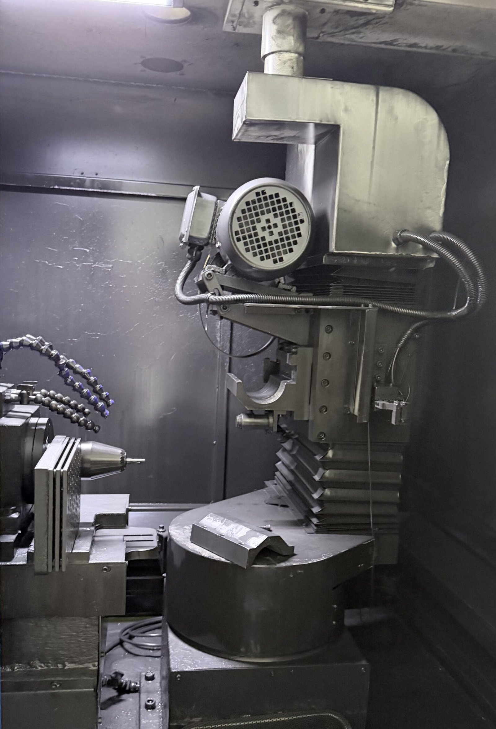
Our CNC machines are Swiss-made units with positioning accuracy of 2 microns. Each machine has five axes of motion: three linear and two rotational. This allows the grinding wheel to approach the blank from any angle. We can create complex flute patterns that would be impossible with manual equipment.
The fluting program starts with a 3D model of the finished burr. Our engineering team designs flute patterns based on the target material. Double cut patterns work best for stainless steel and high-temperature alloys. Single cut patterns suit cast iron and mild steel. Aluminum cut patterns have larger flute spacing to accommodate the material's tendency to gum up cutting edges. We have developed proprietary flute geometries for specific applications. These patterns come from 19 years of testing and customer feedback.
The machine operator loads a sintered blank into the chuck. The CNC program automatically positions it and begins cutting. The grinding wheel is diamond-impregnated with 80-120 grit size. Finer grit creates smoother flutes. Coarser grit cuts faster but leaves rougher surfaces. We balance cutting speed against finish quality.
Coolant flow during fluting prevents thermal damage. Grinding generates heat that can change the carbide's microstructure near the cutting edge. We use water-soluble coolant at 10% concentration. Flow rate is 20 liters per minute focused directly at the cutting zone. The coolant also washes away grinding swarf that could scratch the finished surfaces.
Flute depth directly affects cutting performance. Too shallow and the tool cannot evacuate chips effectively. Too deep and the remaining carbide structure lacks strength. We typically cut flutes to 30-40% of the blank's diameter. Deeper flutes work for softer materials. Shallower flutes suit harder materials that generate smaller chips.
Flute spacing follows mathematical patterns based on the blank's diameter and intended cutting speed. Closer spacing creates more cutting edges but leaves less chip clearance between them. We use computer simulation to optimize spacing for different applications. A burr for stainless steel has different spacing than one for aluminum.
The machine cuts all flutes in a single setup without removing the blank from the chuck. This maintains perfect concentricity. Manual fluting requires multiple setups that introduce alignment errors. Those errors cause vibration during use and accelerate wear.
After fluting, we inspect the cutting edges under 50x magnification. We check for chips, cracks, and grinding burns. The edges should be sharp and uniform. Rounded edges indicate dull grinding wheels. Dark discoloration shows thermal damage. Either defect causes rejection. Our inspection reject rate is under 1%.
Some customers request custom flute patterns. We can accommodate this with programming changes. New patterns require testing to validate performance. We machine prototype burrs and test them in our lab. Cutting force measurements and tool life tests confirm the design before production.
| Flute Parameter | Standard Value | Impact on Performance |
|---|---|---|
| Flute Depth | 30-40% of diameter | Affects chip clearance |
| Flute Spacing | 2-4 mm (varies by size) | Determines cutting edge count |
| Flute Angle | 15-30° | Influences chip flow direction |
| Edge Radius | < 5 microns | Sharp edges cut better |
| Surface Finish | Ra 95%), with exact shrinkage depending on green density, cobalt content, and sintering parameters. Evidence role: general_support; source type: research. Supports: typical dimensional shrinkage during tungsten carbide sintering. |
[^9]: "Tungsten carbide - Wikipedia", https://en.wikipedia.org/wiki/Tungsten_carbide. Diamond grinding wheels are required for machining sintered tungsten carbide due to carbide's extreme hardness (HRA 88-93); diamond, as the hardest known material (10 on Mohs scale vs. tungsten carbide's 9), is one of the few abrasives capable of efficiently cutting and shaping cemented carbide materials. Evidence role: mechanism; source type: research. Supports: the necessity of diamond abrasives for machining tungsten carbide.