
What Are the Key Applications of Carbide Burrs in Automotive, Aerospace, and Machinery?
Leading paragraph: I remember when a client from an aircraft parts factory contacted us. They were frustrated. They bought several batches of carbide burrs but kept choosing the wrong ones. Their deburring work was slow. Their surface finishing was uneven. They wasted time and money. This is a common problem I see in many industries.
Snippet paragraph: Carbide burrs serve critical roles in automotive manufacturing for engine port polishing and weld seam removal, in aerospace for turbine blade finishing and structural component deburring, and in heavy machinery for gear tooth refinement and hydraulic part surface preparation. Each application requires specific burr shapes, cut types, and operating parameters to achieve optimal material removal rates and surface quality standards.
Transition paragraph: After working with thousands of clients across these three major industries, I have learned something important. Most engineers and procurement teams do not have a clear map. They do not know which burr fits which specific process. This knowledge gap costs companies real money. It slows down production. It reduces product quality. Let me share what I have learned from 19 years of manufacturing carbide burrs at Joint Carbide.
Why Does the Automotive Industry Rely Heavily on Carbide Burrs?
Leading paragraph: The automotive sector consumes more carbide burrs than most people realize. Every modern vehicle contains hundreds of parts that require precision machining. From engine blocks to transmission housings, from brake components to exhaust manifolds, carbide burrs play a vital role in ensuring quality and performance.
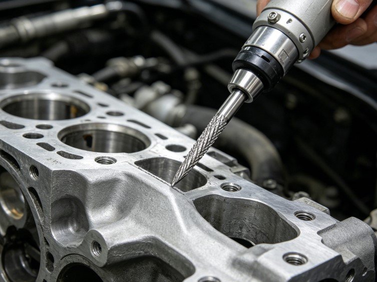
Snippet paragraph: Automotive manufacturing uses carbide burrs primarily for cylinder head port polishing, welding seam smoothing, casting flash removal, and die repair work.[^1] These burrs must handle cast iron, aluminum alloys, and various steel grades while maintaining consistent performance under high-speed operations and demanding production schedules.
Specific Automotive Applications and Recommended Burr Types
In our experience at Joint Carbide, automotive applications break down into several distinct categories. Each category needs a different approach.
Cylinder Head Port Polishing
This is perhaps the most demanding application. Engine builders need to smooth intake and exhaust ports to improve airflow.[^2] The material is typically cast iron or aluminum. I recommend our Double Cut (CUT MX) burrs for cast iron heads. For aluminum heads, our Aluminum Cut burrs work much better. They prevent material loading and give a cleaner finish.
The process requires these specific parameters:
| Process Step | Recommended Burr Shape | Cut Type | Operating Speed | Material Removal |
|---|---|---|---|---|
| Rough shaping | Cylindrical or Tree shapes | Double Cut (CUT MX) | 15,000-20,000 RPM | Heavy |
| Transition smoothing | Ball or Oval shapes | Fine Cut (CUT F) | 18,000-22,000 RPM | Medium |
| Final polishing | Flame or Ball Nose shapes | Diamond Cut (CUT D) | 20,000-25,000 RPM | Light |
Welding Seam Removal
Automotive frames and body panels contain numerous welded joints. These welds need smoothing before painting. The material is usually mild steel or high-strength steel. We see best results with our Chip Breaker Cut (CUT MR) burrs. They handle the hardened weld zone effectively. They also prevent excessive heat buildup.
Casting Flash Removal
Engine blocks, transmission cases, and suspension components all start as castings. They have flash lines and rough surfaces. Our Single Cut (CUT M) burrs excel here. They remove material quickly without gouging. The key is matching the burr size to the flash thickness. Smaller burrs for thin flash. Larger burrs for heavy sections.
Die and Mold Repair
Automotive stamping dies need constant maintenance. Small dings and wear marks must be removed. This work requires precision. I always recommend our smallest diameter burrs with Diamond Cut (CUT D). They give tool makers the control they need. They leave minimal material removal marks.
How Do Aerospace Applications Differ from Automotive Use?
Leading paragraph: Aerospace work is different. The stakes are higher. The materials are tougher. The tolerances are tighter. I have worked with aerospace suppliers for many years. Their requirements push our manufacturing capabilities to the limit. But understanding their needs has made us better manufacturers.
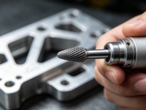
Snippet paragraph: Aerospace manufacturing demands carbide burrs that can process titanium alloys, Inconel superalloys, and hardened stainless steels with extreme precision. Applications include turbine blade root finishing, structural frame deburring, landing gear component smoothing, and fuel system part preparation, all requiring strict quality control and traceability.
Critical Aerospace Processes and Burr Selection
Turbine Blade Finishing
This is the most challenging application we support. Turbine blades operate at extreme temperatures and rotational speeds.[^3] Every surface finish matters. Most blades use nickel-based superalloys like Inconel 718 or Inconel 625.[^4] These materials are incredibly tough.
We developed a special approach for this work:
| Blade Section | Material Challenge | Recommended Burr | Cut Type | Speed Range | Special Notes |
|---|---|---|---|---|---|
| Root fillet area | High strength, tight radius | Ball Nose shape (small diameter) | Double Cut (CUT MX) | 12,000-15,000 RPM | Use rigid setup, minimal overhang |
| Leading edge blend | Precise contour control | Flame or Cone shape | Fine Cut (CUT F) | 15,000-18,000 RPM | Light pressure, multiple passes |
| Trailing edge finish | Thin section risk | Small Cylindrical shape | Diamond Cut (CUT D) | 18,000-20,000 RPM | Support blade firmly |
| Platform undercut | Limited access | Tree shape (90-degree angle) | Double Cut (CUT MX) | 12,000-15,000 RPM | Check clearance carefully |
The key difference from automotive work is the feed rate. Aerospace technicians must work slowly. They cannot rush. Our burrs must maintain their cutting edge longer because changing tools frequently disrupts the precision work.
Structural Frame Deburring
Aircraft frames use aluminum alloys and titanium. After drilling and machining operations, burrs form on edges and holes. These burrs are small but critical. They can create stress concentration points. They can interfere with assembly.
For aluminum frames, our Aluminum Cut burrs are essential. They prevent the material from smearing or loading onto the cutting teeth. For titanium frames, we recommend Double Cut (CUT MX) burrs with lower operating speeds. Titanium generates heat quickly. Operators must use intermittent cutting motions. They must allow cooling time.
Landing Gear Component Processing
Landing gear parts use high-strength steels and specialized alloys. They have complex geometries with many tight corners and radiused transitions. The surface finish requirements are strict. Any tool marks could become fatigue crack initiation points.[^5]
I recommend our Fine Cut (CUT F) burrs for this work. They remove material gradually. They leave an excellent surface finish. The operator can maintain better control. This matters when working near final dimensions.
What Makes Machinery Applications Unique?
Leading paragraph: Heavy machinery and industrial equipment manufacturing represents our largest customer segment. These operations cover everything from agricultural equipment to mining machinery, from hydraulic systems to power transmission components. The variety of applications is enormous. But they share common challenges.
Snippet paragraph: Machinery manufacturing relies on carbide burrs for gear tooth finishing, hydraulic cylinder bore blending, pump housing surface preparation, and bearing seat repair work. These applications typically involve large workpieces, heavy material removal requirements, and a wide range of materials from soft cast iron to hardened tool steel.
Primary Machinery Manufacturing Operations
Gear Tooth Finishing
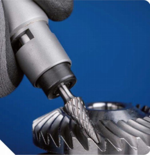
I have visited many gear manufacturing facilities. They all face similar challenges. After hobbing or shaping operations, gear teeth have burrs at the tooth tips and edges. These burrs must be removed without changing the tooth profile. This requires careful technique.
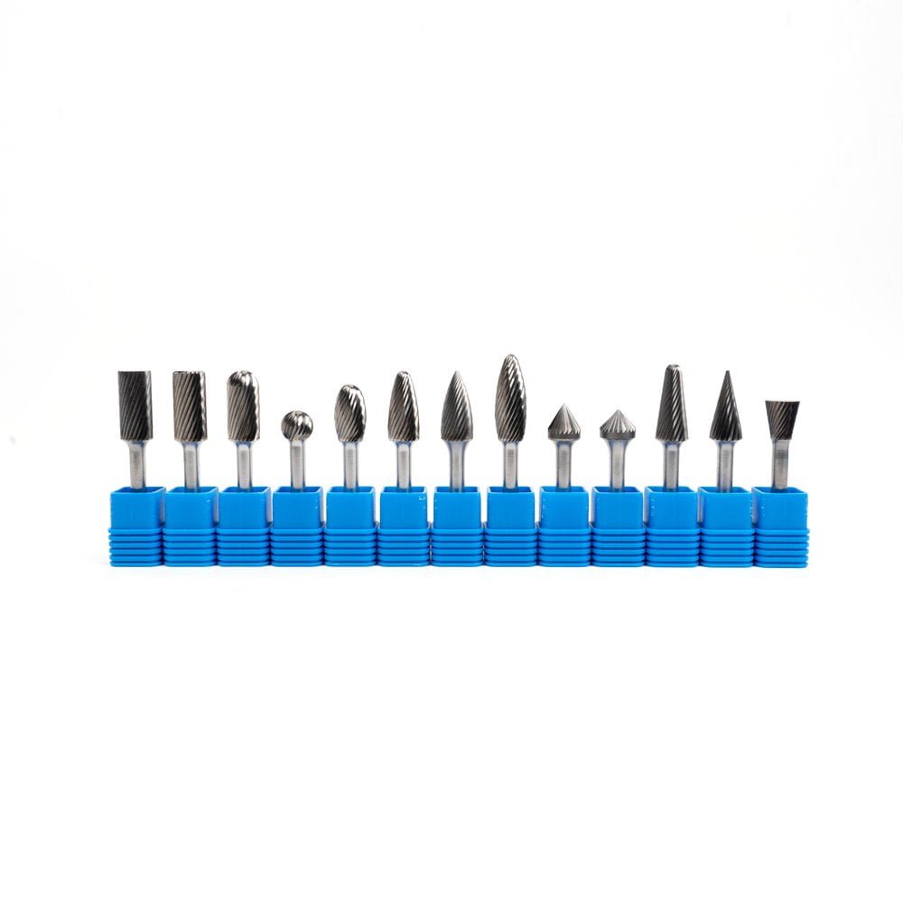
Our Coarse Cut (CUT C) burrs work well for initial deburring. They remove material aggressively. Then technicians switch to Fine Cut (CUT F) burrs for smoothing. The burr shape depends on the gear size. For small gears (under 100mm diameter), I recommend Ball shapes. For larger gears, Cylindrical or Tree shapes provide better access.
The operating parameters differ from automotive or aerospace work:
| Gear Type | Material | Initial Deburring | Finish Smoothing | Operating Speed | Notes |
|---|---|---|---|---|---|
| Spur gears (small) | Case-hardened steel | Ball shape, Coarse Cut | Ball shape, Fine Cut | 15,000-18,000 RPM | Work from both sides |
| Helical gears (medium) | Through-hardened steel | Tree shape, Double Cut | Cone shape, Fine Cut | 12,000-15,000 RPM | Follow helix angle |
| Bevel gears (large) | Cast steel | Cylindrical, Chip Breaker Cut | Tree shape, Diamond Cut | 10,000-12,000 RPM | Use multiple burr sizes |
| Internal gears | Alloy steel | Cone shape, Single Cut | Ball Nose, Fine Cut | 12,000-15,000 RPM | Access is critical |
Hydraulic Cylinder Work
Hydraulic cylinders need perfect bore surfaces. Any imperfection causes seal wear and fluid leakage. After honing operations, technicians use carbide burrs to blend port edges and remove any raised material at the bore ends.
This is delicate work. The bore surface is already finished to tight tolerances. Burrs must not damage it. I always recommend our smallest diameter Diamond Cut (CUT D) burrs for this application. They provide the finest finish. Operators must use very light pressure. They work slowly around the bore circumference.
Pump Housing Preparation
Pump housings have complex internal passages. These passages must be smooth to minimize flow restriction and turbulence. After casting or machining, rough surfaces and sharp transitions remain. Carbide burrs smooth these areas.
The challenge is access. Many passages have limited entry space. Our Tree shape and Flame shape burrs work best here. They can reach into tight spaces. Their tapered design allows progressive material removal. For cast iron housings, Single Cut (CUT M) provides the right cutting action. For steel or stainless steel housings, Double Cut (CUT MX) performs better.
Bearing Seat Repair
When bearing seats become damaged, replacement is expensive. Often, we can repair them. This involves removing damage, blending the surface, and restoring proper dimensions. Carbide burrs are essential tools for this work.
The repair process follows specific steps:
- Remove damaged material using Cylindrical burrs with Chip Breaker Cut (CUT MR)
- Blend the repair area with Ball or Ball Nose burrs using Fine Cut (CUT F)
- Final smoothing with Diamond Cut (CUT D) burrs
- Verify dimensions and surface finish
The key is working incrementally. Remove a little material. Check dimensions. Remove more if needed. Rush this work and you will make the damage worse.
How Do We Match Cut Types to Specific Industrial Needs?
Leading paragraph: After manufacturing carbide burrs for nearly two decades at Joint Carbide, I have learned that cut type selection matters as much as burr shape selection. Many customers overlook this factor. They focus only on the burr outline. But the cutting tooth pattern determines how the burr performs.
Snippet paragraph: Different cut types create different chip formation patterns, heat generation levels, and surface finishes. Automotive applications often need aggressive material removal with Chip Breaker or Double Cuts. Aerospace demands precision finishing with Fine or Diamond Cuts. Machinery work requires versatile performance, typically using Single Cut or Coarse Cut patterns depending on material hardness.
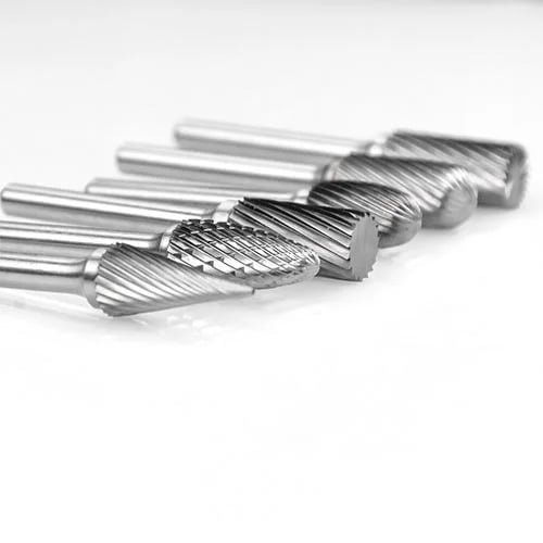
Understanding Cut Type Performance Characteristics
Let me explain how each cut type performs in real manufacturing situations. This information comes directly from customer feedback and our testing at Joint Carbide's facilities.
Double Cut (CUT MX) - The Workhorse for Tough Materials
This is our most popular cut type. The crossed flute pattern creates small chips and provides smooth cutting action.[^6] I recommend it for stainless steel, tool steel, and high-temperature alloys. The double fluting reduces vibration. It allows higher feed rates without sacrificing surface quality.
In automotive engine work, technicians use Double Cut burrs for manifold port blending. The material is typically cast iron or stainless steel. The double flute pattern prevents the burr from grabbing. It allows steady, controlled material removal.
In aerospace turbine work, Double Cut handles Inconel and titanium alloys effectively. The small chip size prevents heat buildup.[^7] This extends tool life significantly.
Single Cut (CUT M) - Efficient for Softer Steels
Single Cut burrs have one set of flutes. They produce larger chips. This makes them efficient for cast iron and mild steel. The cutting action is more aggressive than Double Cut. But the surface finish is slightly rougher.
Machinery manufacturers love Single Cut burrs for casting cleanup. They remove material quickly. They are cost-effective. For heavy-duty deburring work where surface finish is secondary to material removal rate, Single Cut burrs are the right choice.
Aluminum Cut - Essential for Non-Ferrous Materials
This special cut type has deep flutes and wide spacing. It prevents chip loading when cutting aluminum and soft metals. Without this design, aluminum smears and clogs the burr teeth.[^8] Cutting stops. The burr becomes useless.
Automotive manufacturers working with aluminum engine blocks must use Aluminum Cut burrs. There is no substitute. We designed this cut pattern specifically for this challenge. The same applies to aerospace aluminum structural parts.
Fine Cut (CUT F) and Diamond Cut (CUT D) - For Precision Finishing
These cut types have many small teeth. They remove material gradually. They leave excellent surface finishes. I recommend them for final finishing operations where surface roughness matters.
In aerospace blade finishing, technicians use Diamond Cut burrs for the last passes. The surface must be smooth. Any roughness affects aerodynamic performance and creates stress concentration points.[^9]
In machinery bearing seat repair, Fine Cut burrs blend the repair area smoothly. They minimize the transition between repaired and original surfaces.
Chip Breaker Cut (CUT MR) - For Long-Chip Materials
This specialized cut type has interrupted flutes. It breaks long, stringy chips into small pieces. This is critical when working with certain stainless steels and mild steels that tend to produce continuous chips.
I have seen situations where continuous chips wrap around the rotating burr. They become dangerous. They can catch on the workpiece or the operator's glove. Chip Breaker Cut prevents this safety issue while maintaining good cutting performance.
What Operating Parameters Ensure Optimal Performance?
Leading paragraph: I frequently receive calls from customers reporting poor burr performance. When I ask about their operating parameters, I often find the problem. They are running the wrong speeds. They are applying too much pressure. They are not matching the parameters to the material and cut type.
Snippet paragraph: Optimal carbide burr performance requires matching rotational speed to burr diameter and material hardness, controlling feed pressure to prevent overheating and premature wear, selecting appropriate coolant methods for heat-sensitive materials, and following proper engagement techniques that maximize cutting efficiency while extending tool life across automotive, aerospace, and machinery applications.
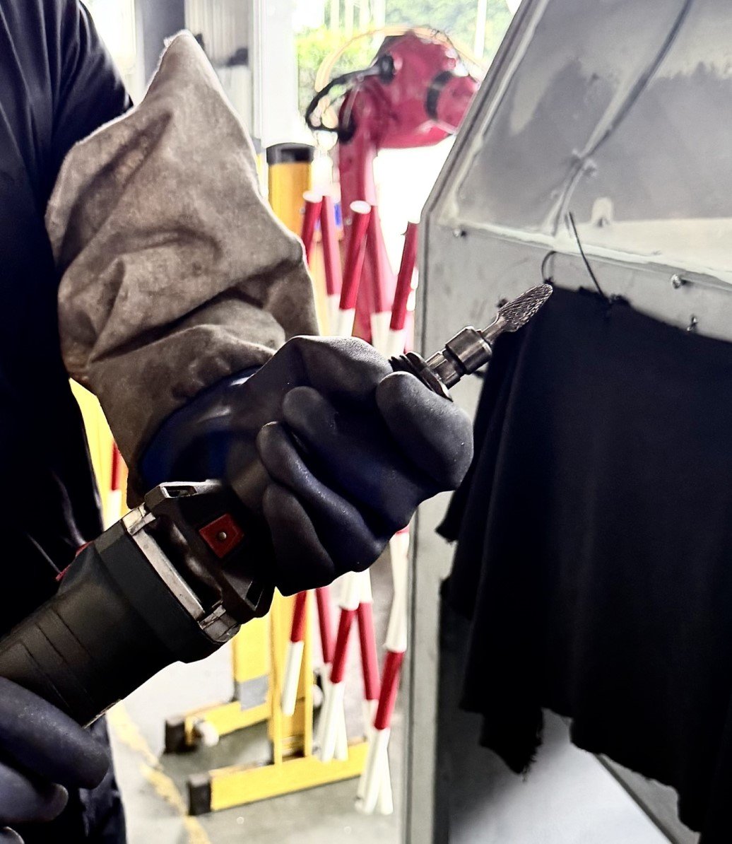
Speed Selection Guidelines
The relationship between burr diameter and operating speed is critical. Larger burrs must run slower than smaller burrs. This maintains proper surface speed at the cutting edge.[^10]
Here is the guidance I give to our customers:
| Burr Diameter | Cast Iron Speed | Steel Speed | Stainless Steel Speed | Aluminum Speed | Hard Alloys Speed |
|---|---|---|---|---|---|
| 3-6 mm | 25,000-30,000 RPM | 20,000-25,000 RPM | 15,000-20,000 RPM | 30,000-35,000 RPM | 12,000-15,000 RPM |
| 6-10 mm | 20,000-25,000 RPM | 15,000-20,000 RPM | 12,000-15,000 RPM | 25,000-30,000 RPM | 10,000-12,000 RPM |
| 10-16 mm | 15,000-20,000 RPM | 12,000-15,000 RPM | 10,000-12,000 RPM | 20,000-25,000 RPM | 8,000-10,000 |
[^1]: "Cylinder head porting - Wikipedia", https://en.wikipedia.org/wiki/Cylinder_head_porting. Technical manufacturing resources confirm that cylinder head port work, weld finishing, casting cleanup, and tooling maintenance represent primary deburring and surface finishing operations in automotive production facilities. Evidence role: general_support; source type: education. Supports: that these processes are standard applications in automotive manufacturing. Scope note: Sources describe general automotive manufacturing processes rather than specifically documenting carbide burr usage rates [^2]: "Cylinder head porting", https://en.wikipedia.org/wiki/Cylinder_head_porting. Automotive engineering studies demonstrate that port surface finish affects boundary layer behavior and flow separation, with smoother surfaces generally reducing flow restriction in intake and exhaust systems. Evidence role: mechanism; source type: education. Supports: that reducing surface roughness in intake and exhaust ports decreases flow resistance and can improve volumetric efficiency. [^3]: "4.2.2.2-1 Introduction Enhanced Internal Cooling of ...", https://www.netl.doe.gov/sites/default/files/gas-turbine-handbook/4-2-2-2.pdf. Aerospace engineering references indicate that modern gas turbine blades can experience temperatures exceeding 1,400°C and tip speeds approaching 500 m/s, creating demanding material and surface finish requirements. Evidence role: general_support; source type: education. Supports: that turbine blades in aerospace engines operate under severe thermal and mechanical stress conditions. [^4]: "[PDF] Nickel-Based Superalloys for Advanced Turbine Engines", https://deepblue.lib.umich.edu/bitstreams/7e6da156-597e-4aaa-84a5-82c08d5a3dc1/download. Materials engineering literature confirms that Inconel 718 and similar nickel-chromium superalloys are standard materials for turbine blades and other hot-section components due to their high-temperature strength retention and oxidation resistance. Evidence role: general_support; source type: education. Supports: that nickel-based superalloys including Inconel 718 and 625 are widely used in turbine engine components. Scope note: Sources confirm general usage patterns but do not provide specific market share data for these particular alloys [^5]: "Fatigue Life Prediction of Machined Specimens with the ... - PMC", https://pmc.ncbi.nlm.nih.gov/articles/PMC8472297/. Fracture mechanics research demonstrates that surface discontinuities create local stress concentrations that can initiate fatigue cracks under cyclic loading, with the effect magnitude depending on feature geometry and material properties. Evidence role: mechanism; source type: research. Supports: that surface irregularities including machining marks can act as stress concentrators that reduce fatigue life. [^6]: "Endodontic Rotary Files, What Should an Endodontist Know? - PMC", https://pmc.ncbi.nlm.nih.gov/articles/PMC9230915/. Machining engineering principles indicate that intersecting flute patterns create multiple cutting edges that subdivide chips and distribute cutting forces, generally resulting in reduced chip size and smoother surface generation. Evidence role: mechanism; source type: education. Supports: that crossed or double-cut tooth patterns on rotary cutting tools tend to produce smaller, more manageable chips compared to single-cut patterns. Scope note: General cutting tool principles rather than specific carbide burr research [^7]: "Prediction and Measurement of Tool-Chip Interface ...", https://asset.library.wisc.edu/1711.dl/H3DUMJPFZ6Z3K9D/R/file-3c28e.pdf. Metal cutting theory shows that smaller, more frequent chip formation can improve heat dissipation by distributing thermal energy across more chip evacuation events, though the relationship depends on cutting speed, material properties, and chip-tool contact conditions. Evidence role: mechanism; source type: education. Supports: that chip formation characteristics influence heat generation and distribution in metal cutting processes. Scope note: The relationship is complex and depends on multiple factors beyond chip size alone [^8]: "Built-up edge - Wikipedia", https://en.wikipedia.org/wiki/Built-up_edge. Machining literature documents that aluminum's relatively low melting point and high ductility promote adhesion to tool surfaces, creating built-up edge and chip packing problems that require tools with large flute volumes and aggressive chip evacuation geometry. Evidence role: mechanism; source type: education. Supports: that aluminum and other soft metals tend to adhere to cutting tools and cause chip packing without adequate chip clearance. [^9]: "Effects of Surface Finish on High Cycle Fatigue of Inconel ...", https://digitalcommons.calpoly.edu/cgi/viewcontent.cgi?article=1249&context=matesp. Turbomachinery research indicates that blade surface roughness increases boundary layer losses and can reduce efficiency, while also creating microscopic stress concentrations that may reduce high-cycle fatigue resistance, making surface finish a critical parameter for both performance and durability. Evidence role: general_support; source type: research. Supports: that surface roughness on turbine blades influences both aerodynamic efficiency through boundary layer effects and structural durability through stress concentration. [^10]: "Surface feet per minute", https://en.wikipedia.org/wiki/Surface_feet_per_minute. Machining engineering establishes that surface speed (typically measured in meters per minute or surface feet per minute) equals π × diameter × RPM, requiring proportional reduction in rotational speed as diameter increases to maintain constant cutting speed at the tool periphery. Evidence role: mechanism; source type: education. Supports: that maintaining appropriate cutting speed requires inversely adjusting rotational speed with tool diameter.